تعلم الوحدات · الدرس 2.19
وحدة حساس الصوت (Sound Sensor Module)
العودة إلى الدروسالتعرف على الحساس
للوحدة خرجان: AO تناظري يعطي جهد إشارة الميكروفون (Microphone) لحظيًا، و DO رقمي يتغير HIGH أو LOW عند بلوغ شدة الصوت حدًا معينًا. يضبط المقاومة المتغيرة (Potentiometer) حساسية ذلك الحد.
لضمان كشف صوتك، حاول تغيير الحساسية بالمقياس الأزرق الدقيق. قد تحتاج عشر دورات كاملة، كل منها 360 درجة، حتى تلاحظ التغيير.
المكونات المطلوبة
- لوحة أردوينو (ELEGOO UNO R3).
- وحدة حساس صوت (Sound Sensor Module).
- أربعة أسلاك أنثى إلى ذكر (Female to Male DuPont Wires).
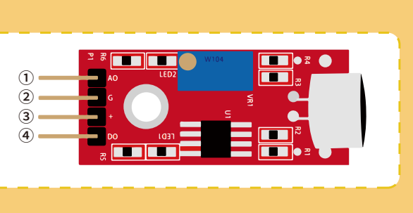
الأطراف: AO خرج تناظري، GND أرضي، VCC تغذية 3.3–5V، و DO خرج رقمي.
المكونات الداخلية
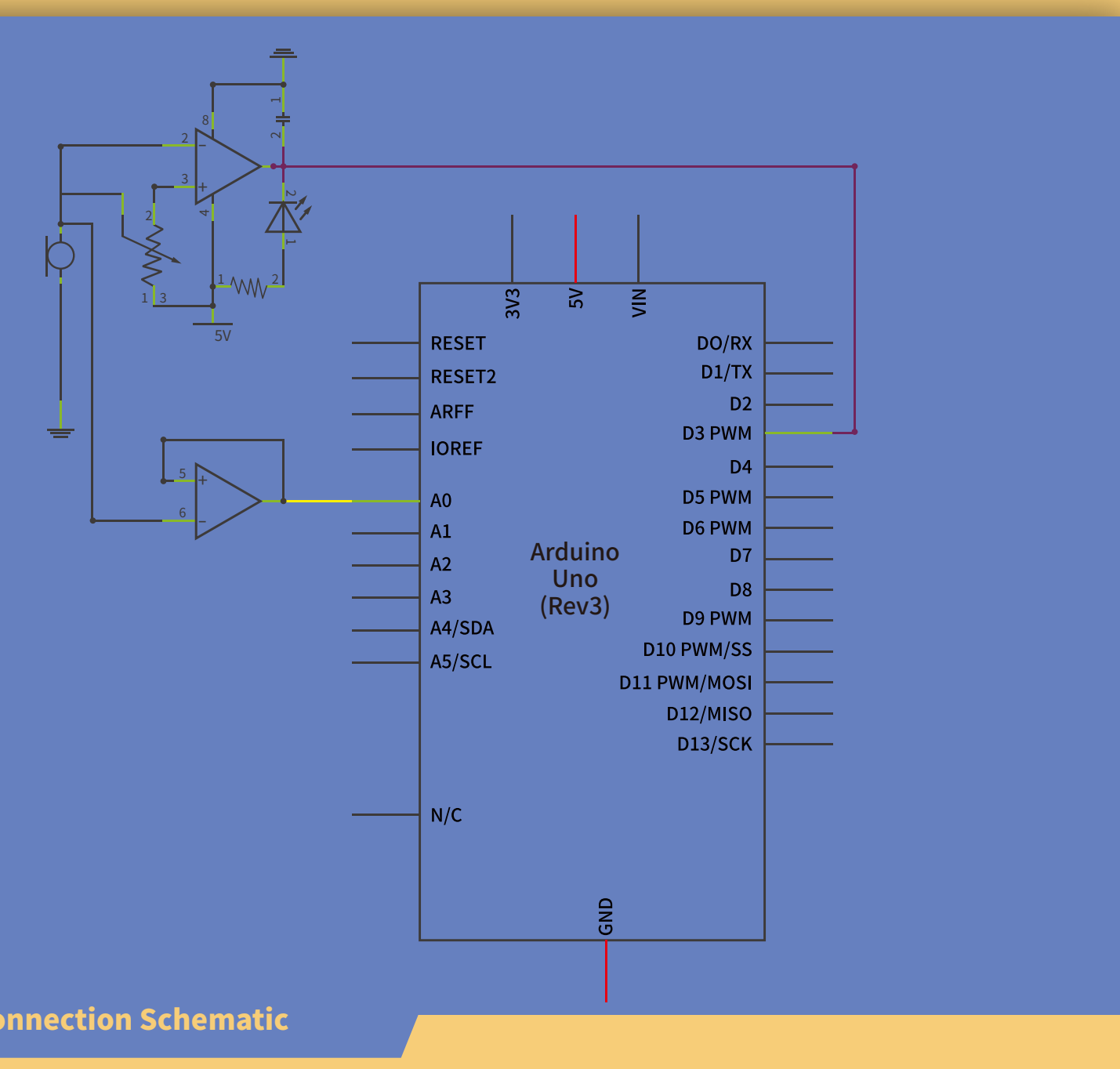
توفر الوحدة وسيلة بسيطة لكشف شدة الصوت، وتستخدم في الأمن والمفاتيح والمراقبة. يمكن ضبط حساسيتها بسهولة. يرسل الميكروفون (Microphone) الإشارة إلى مضخم وكاشف قمة ومرحلة عزل Buffer، ثم تصل إشارة الجهد إلى المتحكم لمعالجتها.
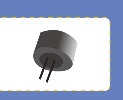
يحول الميكروفون (Microphone) الأصوات أو اهتزاز الهواء إلى إشارة كهربائية، ويوصل بطرفين. يحيط جسم معدني موصل بأجزائه؛ وتغطي سطحه مادة مسامية ملصقة لترشيح الغبار. يمر الصوت خلالها ومن الثقب إلى الغشاء الداخلي.

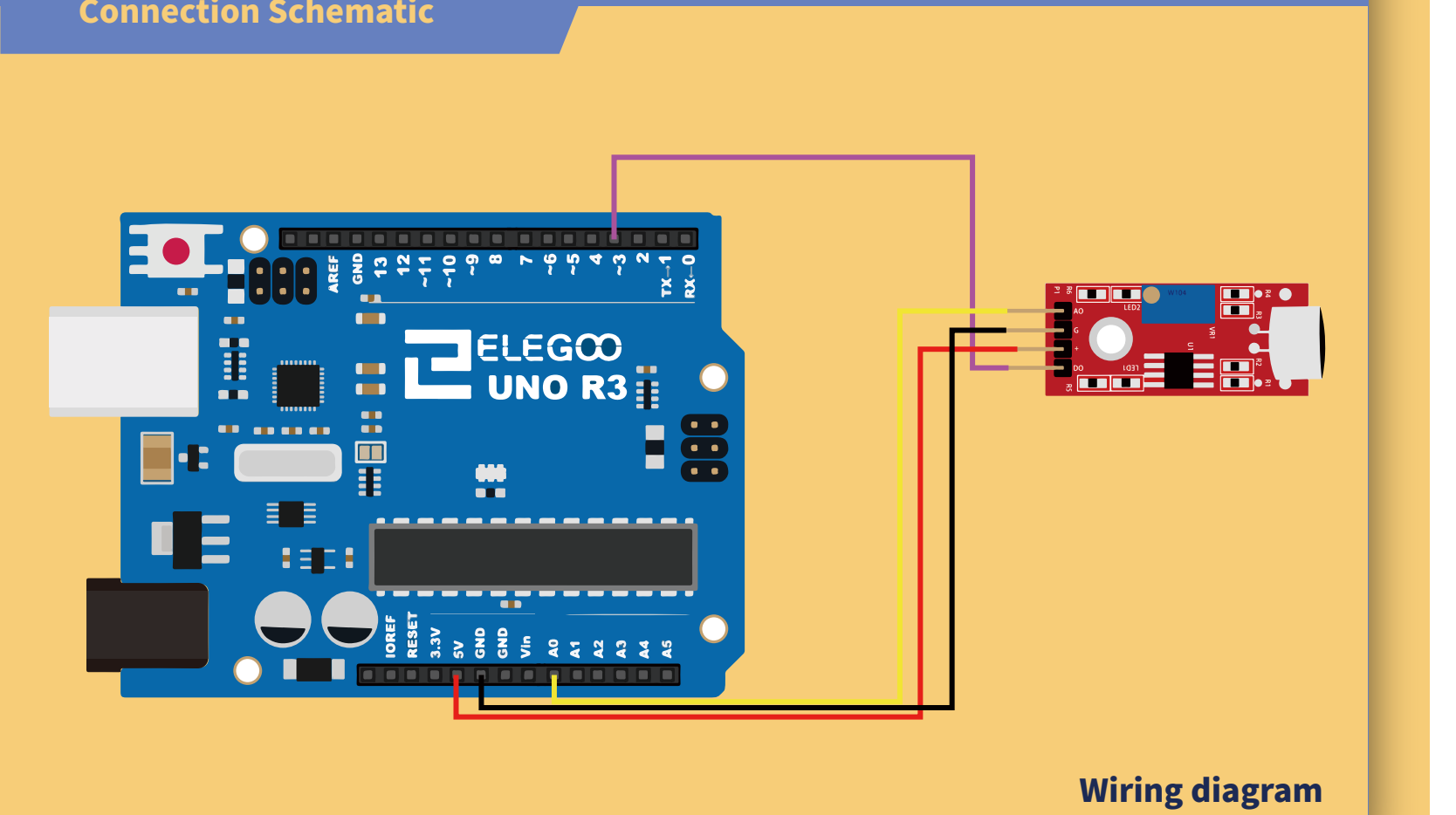
توصيل الدائرة
تشغيل البرنامج وضبط الحساسية
افتح ملف البرنامج Sound_Sensor_Example.ino من ملفات الدرس في بيئة Arduino IDE. بعد إتمام التوصيلات، وصّل لوحة أردوينو (UNO R3 Board) بالحاسوب بكابل توصيل (USB Cable)، ثم اضغط زر Upload (رفع) لنقل البرنامج إلى اللوحة وتشغيله عليها.
إذا تعذر نقل البرنامج إلى اللوحة، فراجع قسم «رفع البرنامج ومعالجة خطأ الاتصال» في الدرس 1.5 «وميض LED وإضافة المكتبات» للتحقق من اتصال USB واختيار نوع اللوحة والمنفذ التسلسلي في بيئة Arduino IDE.
تذكر أن AO إشارة ميكروفون (Microphone) لحظية، و DO خرج رقمي يتغير عند تجاوز عتبة الصوت، وتضبط العتبة بالمقاومة المتغيرة (Potentiometer).
أدر مسمار الضبط بعكس عقارب الساعة باستخدام مفك حتى ينطفئ LED2، ثم اضبط مقياس 10kΩ.
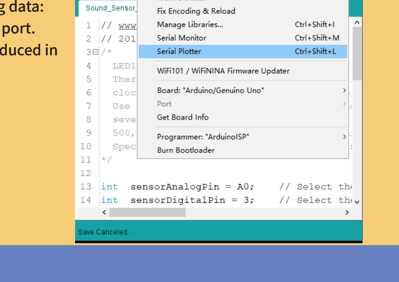
افتح المراقب التسلسلي لعرض البيانات؛ راجع الدرس 2.4 «المراقب التسلسلي» لمعرفة طريقة فتحه وضبط سرعة الاتصال وقراءة البيانات.
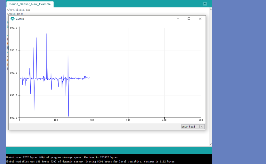
مثال Serial Plotter
عند الكلام في الميكروفون (Microphone) أو النفخ عليه، لاحظ تغير شكل الموجة في الراسم التسلسلي.
الكود
Sound_Sensor_Example/Sound_Sensor_Example.ino
// www.elegoo.com
// 2018.10.24
/*
  LED1 should be lit, showing power. LED2 indicates sound input, and the sensitivity is adjusted by potentiometer.
  There is a tiny screw on the blue potentiometer block that you can use for adjustment. Turning that
  clockwise lowers the potentiometer value, while counter-clockwise raises the potentiometer value.
  Use the potentiometer to adjust the Sound Sensor sensitivity. Turn the potentiometer
  several rotations until you see the LED2 extinguish (or just faintly blink). This might be slightly greater than
  500, if you are also watching Serial Monitor (inital adjustment), or, Serial Plotter (the latter is prefererd for observation).
  Special thanks to user CRomer, for his input and hard work!
*/

int  sensorAnalogPin = A0;    // Select the Arduino input pin to accept the Sound Sensor's analog output
int  sensorDigitalPin = 3;    // Select the Arduino input pin to accept the Sound Sensor's digital output
int  analogValue = 0;         // Define variable to store the analog value coming from the Sound Sensor
int  digitalValue;            // Define variable to store the digital value coming from the Sound Sensor
int  Led13 = 13;              // Define LED port; this is the LED built in to the Arduino (labled L)
                              // When D0 from the Sound Sensor (connnected to pin 7 on the
                              // Arduino) sends High (voltage present), L will light up. In practice, you
                              // should see LED13 on the Arduino blink when LED2 on the Sensor is 100% lit.


void setup()
{
  Serial.begin(9600);               // The IDE settings for Serial Monitor/Plotter (preferred) must match this speed
  pinMode(sensorDigitalPin,INPUT);  // Define pin 3 as an input port, to accept digital input
  pinMode(Led13,OUTPUT);            // Define LED13 as an output port, to indicate digital trigger reached
}

void loop(){
  analogValue = analogRead(sensorAnalogPin); // Read the value of the analog interface A0 assigned to digitalValue
  digitalValue=digitalRead(sensorDigitalPin); // Read the value of the digital interface 7 assigned to digitalValue
  Serial.println(analogValue); // Send the analog value to the serial transmit interface

  if(digitalValue==HIGH)      // When the Sound Sensor sends signla, via voltage present, light LED13 (L)
  {
    digitalWrite(Led13,HIGH);
  }
  else
  {
    digitalWrite(Led13,LOW);
  }

  delay(50);                  // Slight pause so that we don't overwhelm the serial interface
}