تعلم الوحدات · الدرس 2.20
وحدة التعرف بالترددات الراديوية (RC522 RFID Module)
العودة إلى الدروسالتعرف على RC522
ستتعلم تشغيل قارئ البطاقات (RC522 RFID Module) مع UNO R3. تتواصل الوحدة عبر ناقل الواجهة الطرفية التسلسلية SPI مع Arduino و Raspberry Pi و BeagleBoard وغيرها.
المكونات المطلوبة
- لوحة أردوينو (ELEGOO UNO R3).
- وحدة التعرف بالترددات الراديوية (RC522 RFID Module).
- سبعة أسلاك أنثى إلى ذكر (Female to Male DuPont Wires).
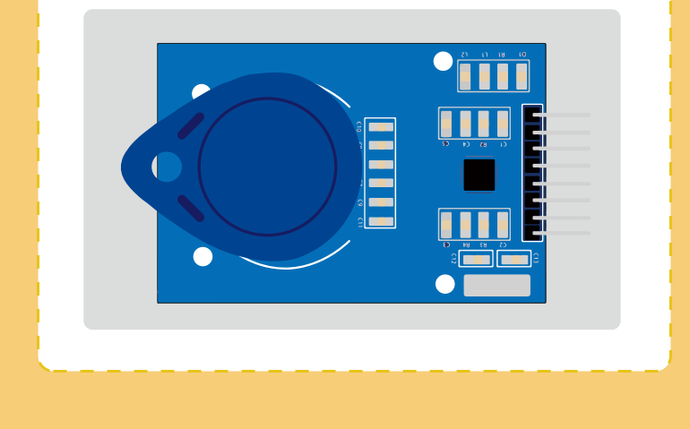
MFRC522
قارئ وكاتب متكامل للاتصال دون تلامس عند 13.56MHz، يدعم ISO14443A/MIFARE. تقود مرحلة الإرسال هوائيًا للتواصل مع البطاقات والمستجيبات المتوافقة دون دوائر نشطة إضافية. وتزيل مرحلة الاستقبال تضمين الإشارة وتفك ترميزها. تعالج المرحلة الرقمية إطارات ISO/IEC14443A وكشف الأخطاء عبر Parity و CRC.
يدعم MIFARE Classic، ومنها MIFARE Standard، وسرعة نقل حتى 848kbit/s في الاتجاهين. الواجهات المضيفة المتاحة SPI و UART تسلسلي مشابه لـ RS232 بمستويات جهد التغذية، و I2C.
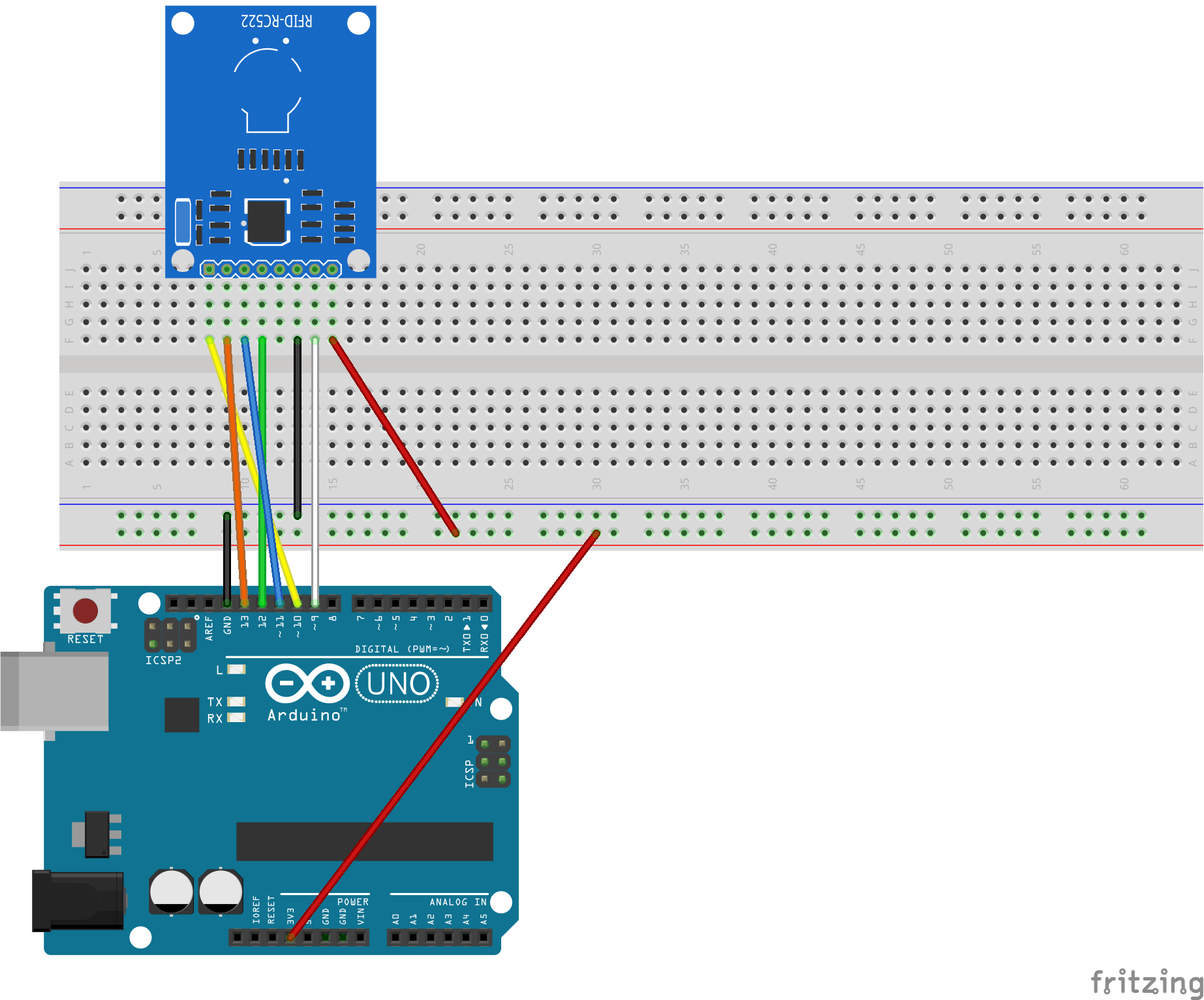
التوصيل
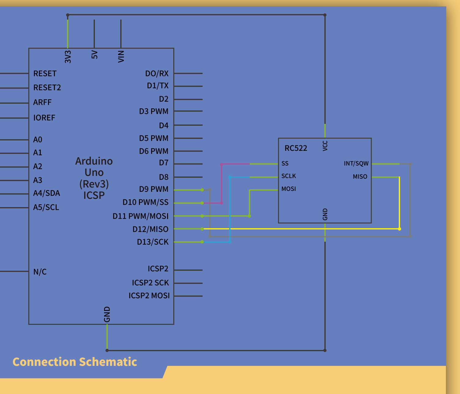
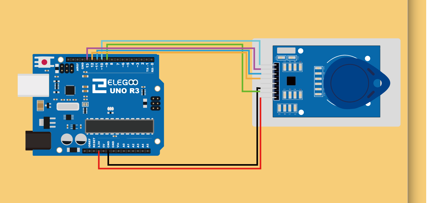
البرنامج ومنافذ SPI
قبل رفع البرنامج، تأكد من توفر مكتبة rfid في بيئة Arduino IDE. إذا لم تكن مثبتة أو ظهرت رسالة تشير إلى مكتبة مفقودة، فاتبع خطوات التثبيت في قسم «ما هي المكتبات؟» وطرق تثبيتها في الدرس 1.5 «وميض LED وإضافة المكتبات».
افتح ملف البرنامج MF-RC522_RFID.ino من ملفات الدرس في بيئة Arduino IDE. بعد إتمام التوصيلات، وصّل لوحة أردوينو (UNO R3 Board) بالحاسوب بكابل توصيل (USB Cable)، ثم اضغط زر Upload (رفع) لنقل البرنامج إلى اللوحة وتشغيله عليها.
إذا تعذر نقل البرنامج إلى اللوحة، فراجع قسم «رفع البرنامج ومعالجة خطأ الاتصال» في الدرس 1.5 «وميض LED وإضافة المكتبات» للتحقق من اتصال USB واختيار نوع اللوحة والمنفذ التسلسلي في بيئة Arduino IDE.
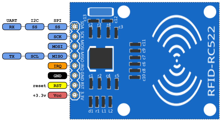
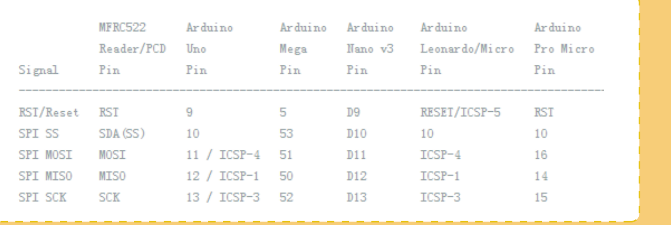
تختلف مواقع منافذ SPI بين الشرائح واللوحات، فتحتاج تعديل التعريفات لتطابقها. في المثال RST_PIN هو 9 و SS_PIN هو 10.
يفحص البرنامج وجود بطاقة جديدة وإمكان قراءة رقمها، ويعود من الدالة إذا فشل أحد الشرطين:
if (!mfrc522.PICC_IsNewCardPresent() || !mfrc522.PICC_ReadCardSerial()) {

  return;

}
NOT المنطقي !
يعكس النتيجة: true إذا كان المعامل false، و false إذا كان true.
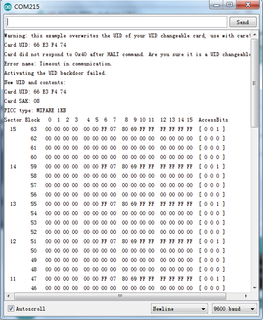
افتح Serial Monitor لعرض بيانات البطاقة؛ راجع الدرس 2.4 «المراقب التسلسلي» لمعرفة طريقة فتحه وضبط سرعة الاتصال وقراءة البيانات.
الكود
MF-RC522_RFID/MF-RC522_RFID.ino
//www.elegoo.com
//2016.12.09

/*
 * --------------------------------------------------------------------------------------------------------------------
 * Example to change UID of changeable MIFARE card.
 * --------------------------------------------------------------------------------------------------------------------
 * This is a MFRC522 library example; For further details and other examples see: https://github.com/miguelbalboa/rfid
 *
 * This sample shows how to set the UID on a UID changeable MIFARE card.
 * NOTE: for more informations read the README.rst
 *
 * @author Tom Clement
 * @license Released into the public domain.
 *
 * Typical pin layout used:
 * -----------------------------------------------------------------------------------------
 *             MFRC522      Arduino       Arduino   Arduino    Arduino          Arduino
 *             Reader/PCD   Uno           Mega      Nano v3    Leonardo/Micro   Pro Micro
 * Signal      Pin          Pin           Pin       Pin        Pin              Pin
 * -----------------------------------------------------------------------------------------
 * RST/Reset   RST          9             5         D9         RESET/ICSP-5     RST
 * SPI SS      SDA(SS)      10            53        D10        10               10
 * SPI MOSI    MOSI         11 / ICSP-4   51        D11        ICSP-4           16
 * SPI MISO    MISO         12 / ICSP-1   50        D12        ICSP-1           14
 * SPI SCK     SCK          13 / ICSP-3   52        D13        ICSP-3           15
 */

#include <SPI.h>
#include <MFRC522.h>

#define RST_PIN   9     // Configurable, see typical pin layout above
#define SS_PIN    10    // Configurable, see typical pin layout above

MFRC522 mfrc522(SS_PIN, RST_PIN);   // Create MFRC522 instance

/* Set your new UID here! */
#define NEW_UID {0xDE, 0xAD, 0xBE, 0xEF}

MFRC522::MIFARE_Key key;

void setup() {
  Serial.begin(9600);  // Initialize serial communications with the PC
  while (!Serial);     // Do nothing if no serial port is opened (added for Arduinos based on ATMEGA32U4)
  SPI.begin();         // Init SPI bus
  mfrc522.PCD_Init();  // Init MFRC522 card
  Serial.println(F("Warning: this example overwrites the UID of your UID changeable card, use with care!"));

  // Prepare key - all keys are set to FFFFFFFFFFFFh at chip delivery from the factory.
  for (byte i = 0; i < 6; i++) {
    key.keyByte[i] = 0xFF;
  }
}

// Setting the UID can be as simple as this:
//void loop() {
//  byte newUid[] = NEW_UID;
//  if ( mfrc522.MIFARE_SetUid(newUid, (byte)4, true) ) {
//    Serial.println("Wrote new UID to card.");
//  }
//  delay(1000);
//}

// But of course this is a more proper approach
void loop() {

  // Look for new cards, and select one if present
  if ( ! mfrc522.PICC_IsNewCardPresent() || ! mfrc522.PICC_ReadCardSerial() ) {
    delay(50);
    return;
  }

  // Now a card is selected. The UID and SAK is in mfrc522.uid.

  // Dump UID
  Serial.print(F("Card UID:"));
  for (byte i = 0; i < mfrc522.uid.size; i++) {
    Serial.print(mfrc522.uid.uidByte[i] < 0x10 ? " 0" : " ");
    Serial.print(mfrc522.uid.uidByte[i], HEX);
  }
  Serial.println();

  // Dump PICC type
//  MFRC522::PICC_Type piccType = mfrc522.PICC_GetType(mfrc522.uid.sak);
//  Serial.print(F("PICC type: "));
//  Serial.print(mfrc522.PICC_GetTypeName(piccType));
//  Serial.print(F(" (SAK "));
//  Serial.print(mfrc522.uid.sak);
//  Serial.print(")\r\n");
//  if (  piccType != MFRC522::PICC_TYPE_MIFARE_MINI
//    &&  piccType != MFRC522::PICC_TYPE_MIFARE_1K
//    &&  piccType != MFRC522::PICC_TYPE_MIFARE_4K) {
//    Serial.println(F("This sample only works with MIFARE Classic cards."));
//    return;
//  }

  // Set new UID
  byte newUid[] = NEW_UID;
  if ( mfrc522.MIFARE_SetUid(newUid, (byte)4, true) ) {
    Serial.println(F("Wrote new UID to card."));
  }

  // Halt PICC and re-select it so DumpToSerial doesn't get confused
  mfrc522.PICC_HaltA();
  if ( ! mfrc522.PICC_IsNewCardPresent() || ! mfrc522.PICC_ReadCardSerial() ) {
    return;
  }

  // Dump the new memory contents
  Serial.println(F("New UID and contents:"));
  mfrc522.PICC_DumpToSerial(&(mfrc522.uid));

  delay(2000);
}
rfid/examples/ChangeUID/ChangeUID.ino
/*
 * --------------------------------------------------------------------------------------------------------------------
 * Example to change UID of changeable MIFARE card.
 * --------------------------------------------------------------------------------------------------------------------
 * This is a MFRC522 library example; for further details and other examples see: https://github.com/miguelbalboa/rfid
 *
 * This sample shows how to set the UID on a UID changeable MIFARE card.
 * NOTE: for more informations read the README.rst
 *
 * @author Tom Clement
 * @license Released into the public domain.
 *
 * Typical pin layout used:
 * -----------------------------------------------------------------------------------------
 *             MFRC522      Arduino       Arduino   Arduino    Arduino          Arduino
 *             Reader/PCD   Uno           Mega      Nano v3    Leonardo/Micro   Pro Micro
 * Signal      Pin          Pin           Pin       Pin        Pin              Pin
 * -----------------------------------------------------------------------------------------
 * RST/Reset   RST          9             5         D9         RESET/ICSP-5     RST
 * SPI SS      SDA(SS)      10            53        D10        10               10
 * SPI MOSI    MOSI         11 / ICSP-4   51        D11        ICSP-4           16
 * SPI MISO    MISO         12 / ICSP-1   50        D12        ICSP-1           14
 * SPI SCK     SCK          13 / ICSP-3   52        D13        ICSP-3           15
 */

#include <SPI.h>
#include <MFRC522.h>

#define RST_PIN   9     // Configurable, see typical pin layout above
#define SS_PIN    10    // Configurable, see typical pin layout above

MFRC522 mfrc522(SS_PIN, RST_PIN);   // Create MFRC522 instance

/* Set your new UID here! */
#define NEW_UID {0xDE, 0xAD, 0xBE, 0xEF}

MFRC522::MIFARE_Key key;

void setup() {
  Serial.begin(9600);  // Initialize serial communications with the PC
  while (!Serial);     // Do nothing if no serial port is opened (added for Arduinos based on ATMEGA32U4)
  SPI.begin();         // Init SPI bus
  mfrc522.PCD_Init();  // Init MFRC522 card
  Serial.println(F("Warning: this example overwrites the UID of your UID changeable card, use with care!"));

  // Prepare key - all keys are set to FFFFFFFFFFFFh at chip delivery from the factory.
  for (byte i = 0; i < 6; i++) {
    key.keyByte[i] = 0xFF;
  }
}

// Setting the UID can be as simple as this:
//void loop() {
//  byte newUid[] = NEW_UID;
//  if ( mfrc522.MIFARE_SetUid(newUid, (byte)4, true) ) {
//    Serial.println("Wrote new UID to card.");
//  }
//  delay(1000);
//}

// But of course this is a more proper approach
void loop() {

  // Look for new cards, and select one if present
  if ( ! mfrc522.PICC_IsNewCardPresent() || ! mfrc522.PICC_ReadCardSerial() ) {
    delay(50);
    return;
  }

  // Now a card is selected. The UID and SAK is in mfrc522.uid.

  // Dump UID
  Serial.print(F("Card UID:"));
  for (byte i = 0; i < mfrc522.uid.size; i++) {
    Serial.print(mfrc522.uid.uidByte[i] < 0x10 ? " 0" : " ");
    Serial.print(mfrc522.uid.uidByte[i], HEX);
  }
  Serial.println();

  // Dump PICC type
//  MFRC522::PICC_Type piccType = mfrc522.PICC_GetType(mfrc522.uid.sak);
//  Serial.print(F("PICC type: "));
//  Serial.print(mfrc522.PICC_GetTypeName(piccType));
//  Serial.print(F(" (SAK "));
//  Serial.print(mfrc522.uid.sak);
//  Serial.print(")\r\n");
//  if (  piccType != MFRC522::PICC_TYPE_MIFARE_MINI
//    &&  piccType != MFRC522::PICC_TYPE_MIFARE_1K
//    &&  piccType != MFRC522::PICC_TYPE_MIFARE_4K) {
//    Serial.println(F("This sample only works with MIFARE Classic cards."));
//    return;
//  }

  // Set new UID
  byte newUid[] = NEW_UID;
  if ( mfrc522.MIFARE_SetUid(newUid, (byte)4, true) ) {
    Serial.println(F("Wrote new UID to card."));
  }

  // Halt PICC and re-select it so DumpToSerial doesn't get confused
  mfrc522.PICC_HaltA();
  if ( ! mfrc522.PICC_IsNewCardPresent() || ! mfrc522.PICC_ReadCardSerial() ) {
    return;
  }

  // Dump the new memory contents
  Serial.println(F("New UID and contents:"));
  mfrc522.PICC_DumpToSerial(&(mfrc522.uid));

  delay(2000);
}
rfid/examples/DumpInfo/DumpInfo.ino
/*
 * --------------------------------------------------------------------------------------------------------------------
 * Example sketch/program showing how to read data from a PICC to serial.
 * --------------------------------------------------------------------------------------------------------------------
 * This is a MFRC522 library example; for further details and other examples see: https://github.com/miguelbalboa/rfid
 *
 * Example sketch/program showing how to read data from a PICC (that is: a RFID Tag or Card) using a MFRC522 based RFID
 * Reader on the Arduino SPI interface.
 *
 * When the Arduino and the MFRC522 module are connected (see the pin layout below), load this sketch into Arduino IDE
 * then verify/compile and upload it. To see the output: use Tools, Serial Monitor of the IDE (hit Ctrl+Shft+M). When
 * you present a PICC (that is: a RFID Tag or Card) at reading distance of the MFRC522 Reader/PCD, the serial output
 * will show the ID/UID, type and any data blocks it can read. Note: you may see "Timeout in communication" messages
 * when removing the PICC from reading distance too early.
 *
 * If your reader supports it, this sketch/program will read all the PICCs presented (that is: multiple tag reading).
 * So if you stack two or more PICCs on top of each other and present them to the reader, it will first output all
 * details of the first and then the next PICC. Note that this may take some time as all data blocks are dumped, so
 * keep the PICCs at reading distance until complete.
 *
 * @license Released into the public domain.
 *
 * Typical pin layout used:
 * -----------------------------------------------------------------------------------------
 *             MFRC522      Arduino       Arduino   Arduino    Arduino          Arduino
 *             Reader/PCD   Uno           Mega      Nano v3    Leonardo/Micro   Pro Micro
 * Signal      Pin          Pin           Pin       Pin        Pin              Pin
 * -----------------------------------------------------------------------------------------
 * RST/Reset   RST          9             5         D9         RESET/ICSP-5     RST
 * SPI SS      SDA(SS)      10            53        D10        10               10
 * SPI MOSI    MOSI         11 / ICSP-4   51        D11        ICSP-4           16
 * SPI MISO    MISO         12 / ICSP-1   50        D12        ICSP-1           14
 * SPI SCK     SCK          13 / ICSP-3   52        D13        ICSP-3           15
 */

#include <SPI.h>
#include <MFRC522.h>

#define RST_PIN         9          // Configurable, see typical pin layout above
#define SS_PIN          10         // Configurable, see typical pin layout above

MFRC522 mfrc522(SS_PIN, RST_PIN);  // Create MFRC522 instance

void setup() {
	Serial.begin(9600);		// Initialize serial communications with the PC
	while (!Serial);		// Do nothing if no serial port is opened (added for Arduinos based on ATMEGA32U4)
	SPI.begin();			// Init SPI bus
	mfrc522.PCD_Init();		// Init MFRC522
	mfrc522.PCD_DumpVersionToSerial();	// Show details of PCD - MFRC522 Card Reader details
	Serial.println(F("Scan PICC to see UID, SAK, type, and data blocks..."));
}

void loop() {
	// Look for new cards
	if ( ! mfrc522.PICC_IsNewCardPresent()) {
		return;
	}

	// Select one of the cards
	if ( ! mfrc522.PICC_ReadCardSerial()) {
		return;
	}

	// Dump debug info about the card; PICC_HaltA() is automatically called
	mfrc522.PICC_DumpToSerial(&(mfrc522.uid));
}
rfid/examples/firmware_check/firmware_check.ino
/*
 * --------------------------------------------------------------------------------------------------------------------
 * Example sketch/program to test your firmware.
 * --------------------------------------------------------------------------------------------------------------------
 * This is a MFRC522 library example; for further details and other examples see: https://github.com/miguelbalboa/rfid
 *
 * This example test the firmware of your MFRC522 reader module, only known version can be checked. If the test passed
 * it do not mean that your module is faultless! Some modules have bad or broken antennas or the PICC is broken.
 * NOTE: for more informations read the README.rst
 *
 * @author Rotzbua
 * @license Released into the public domain.
 *
 * Typical pin layout used:
 * -----------------------------------------------------------------------------------------
 *             MFRC522      Arduino       Arduino   Arduino    Arduino          Arduino
 *             Reader/PCD   Uno           Mega      Nano v3    Leonardo/Micro   Pro Micro
 * Signal      Pin          Pin           Pin       Pin        Pin              Pin
 * -----------------------------------------------------------------------------------------
 * RST/Reset   RST          9             5         D9         RESET/ICSP-5     RST
 * SPI SS      SDA(SS)      10            53        D10        10               10
 * SPI MOSI    MOSI         11 / ICSP-4   51        D11        ICSP-4           16
 * SPI MISO    MISO         12 / ICSP-1   50        D12        ICSP-1           14
 * SPI SCK     SCK          13 / ICSP-3   52        D13        ICSP-3           15
 */

#include <SPI.h>
#include <MFRC522.h>

#define RST_PIN         9          // Configurable, see typical pin layout above
#define SS_PIN          10         // Configurable, see typical pin layout above

MFRC522 mfrc522(SS_PIN, RST_PIN);  // Create MFRC522 instance

/**
 * Check firmware only once at startup
 */
void setup() {
  Serial.begin(9600);   // Initialize serial communications with the PC
  while (!Serial);      // Do nothing if no serial port is opened (added for Arduinos based on ATMEGA32U4)
  SPI.begin();          // Init SPI bus
  mfrc522.PCD_Init();   // Init MFRC522 module

  Serial.println(F("*****************************"));
  Serial.println(F("MFRC522 Digital self test"));
  Serial.println(F("*****************************"));
  mfrc522.PCD_DumpVersionToSerial();  // Show version of PCD - MFRC522 Card Reader
  Serial.println(F("-----------------------------"));
  Serial.println(F("Only known versions supported"));
  Serial.println(F("-----------------------------"));
  Serial.println(F("Performing test..."));
  bool result = mfrc522.PCD_PerformSelfTest(); // perform the test
  Serial.println(F("-----------------------------"));
  Serial.print(F("Result: "));
  if (result)
    Serial.println(F("OK"));
  else
    Serial.println(F("DEFECT or UNKNOWN"));
  Serial.println();
}

void loop() {} // nothing to do
rfid/examples/FixBrickedUID/FixBrickedUID.ino
/*
 * --------------------------------------------------------------------------------------------------------------------
 * Example sketch/program to fix a broken UID changeable MIFARE cards.
 * --------------------------------------------------------------------------------------------------------------------
 * This is a MFRC522 library example; for further details and other examples see: https://github.com/miguelbalboa/rfid
 *
 * This sample shows how to fix a broken UID changeable MIFARE cards that have a corrupted sector 0.
 *
 * @author Tom Clement
 * @license Released into the public domain.
 *
 * Typical pin layout used:
 * -----------------------------------------------------------------------------------------
 *             MFRC522      Arduino       Arduino   Arduino    Arduino          Arduino
 *             Reader/PCD   Uno           Mega      Nano v3    Leonardo/Micro   Pro Micro
 * Signal      Pin          Pin           Pin       Pin        Pin              Pin
 * -----------------------------------------------------------------------------------------
 * RST/Reset   RST          9             5         D9         RESET/ICSP-5     RST
 * SPI SS      SDA(SS)      10            53        D10        10               10
 * SPI MOSI    MOSI         11 / ICSP-4   51        D11        ICSP-4           16
 * SPI MISO    MISO         12 / ICSP-1   50        D12        ICSP-1           14
 * SPI SCK     SCK          13 / ICSP-3   52        D13        ICSP-3           15
 */

#include <SPI.h>
#include <MFRC522.h>

#define RST_PIN   9     // Configurable, see typical pin layout above
#define SS_PIN    10    // Configurable, see typical pin layout above

MFRC522 mfrc522(SS_PIN, RST_PIN);   // Create MFRC522 instance

MFRC522::MIFARE_Key key;

void setup() {
  Serial.begin(9600);  // Initialize serial communications with the PC
  while (!Serial);     // Do nothing if no serial port is opened (added for Arduinos based on ATMEGA32U4)
  SPI.begin();         // Init SPI bus
  mfrc522.PCD_Init();  // Init MFRC522 card
  Serial.println(F("Warning: this example clears your mifare UID, use with care!"));

  // Prepare key - all keys are set to FFFFFFFFFFFFh at chip delivery from the factory.
  for (byte i = 0; i < 6; i++) {
    key.keyByte[i] = 0xFF;
  }
}

void loop() {
  if ( mfrc522.MIFARE_UnbrickUidSector(false) ) {
    Serial.println(F("Cleared sector 0, set UID to 1234. Card should be responsive again now."));
  }
  delay(1000);
}
rfid/examples/MifareClassicValueBlock/MifareClassicValueBlock.ino
/**
 * ----------------------------------------------------------------------------
 * This is a MFRC522 library example; see https://github.com/miguelbalboa/rfid
 * for further details and other examples.
 *
 * NOTE: The library file MFRC522.h has a lot of useful info. Please read it.
 *
 * Released into the public domain.
 * ----------------------------------------------------------------------------
 * This sample shows how to setup blocks on a MIFARE Classic PICC (= card/tag)
 * to be in "Value Block" mode: in this mode the operations Increment/Decrement,
 * Restore and Transfer can be used.
 *
 * BEWARE: Data will be written to the PICC, in sector #1 (blocks #4 to #7).
 *
 *
 * Typical pin layout used:
 * -----------------------------------------------------------------------------------------
 *             MFRC522      Arduino       Arduino   Arduino    Arduino          Arduino
 *             Reader/PCD   Uno           Mega      Nano v3    Leonardo/Micro   Pro Micro
 * Signal      Pin          Pin           Pin       Pin        Pin              Pin
 * -----------------------------------------------------------------------------------------
 * RST/Reset   RST          9             5         D9         RESET/ICSP-5     RST
 * SPI SS      SDA(SS)      10            53        D10        10               10
 * SPI MOSI    MOSI         11 / ICSP-4   51        D11        ICSP-4           16
 * SPI MISO    MISO         12 / ICSP-1   50        D12        ICSP-1           14
 * SPI SCK     SCK          13 / ICSP-3   52        D13        ICSP-3           15
 *
 */

#include <SPI.h>
#include <MFRC522.h>

#define RST_PIN         9           // Configurable, see typical pin layout above
#define SS_PIN          10          // Configurable, see typical pin layout above

MFRC522 mfrc522(SS_PIN, RST_PIN);   // Create MFRC522 instance.

MFRC522::MIFARE_Key key;

/**
 * Initialize.
 */
void setup() {
    Serial.begin(9600);	// Initialize serial communications with the PC
    while (!Serial);    // Do nothing if no serial port is opened (added for Arduinos based on ATMEGA32U4)
    SPI.begin();		// Init SPI bus
    mfrc522.PCD_Init();	// Init MFRC522 card

    // Prepare the key (used both as key A and as key B)
    // using FFFFFFFFFFFFh which is the default at chip delivery from the factory
    for (byte i = 0; i < 6; i++) {
        key.keyByte[i] = 0xFF;
    }

    Serial.println(F("Scan a MIFARE Classic PICC to demonstrate Value Block mode."));
    Serial.print(F("Using key (for A and B):"));
    dump_byte_array(key.keyByte, MFRC522::MF_KEY_SIZE);
    Serial.println();

    Serial.println(F("BEWARE: Data will be written to the PICC, in sector #1"));
}

/**
 * Main loop.
 */
void loop() {
    // Look for new cards
    if ( ! mfrc522.PICC_IsNewCardPresent())
        return;

    // Select one of the cards
    if ( ! mfrc522.PICC_ReadCardSerial())
        return;

    // Show some details of the PICC (that is: the tag/card)
    Serial.print(F("Card UID:"));
    dump_byte_array(mfrc522.uid.uidByte, mfrc522.uid.size);
    Serial.println();
    Serial.print(F("PICC type: "));
    MFRC522::PICC_Type piccType = mfrc522.PICC_GetType(mfrc522.uid.sak);
    Serial.println(mfrc522.PICC_GetTypeName(piccType));

    // Check for compatibility
    if (    piccType != MFRC522::PICC_TYPE_MIFARE_MINI
        &&  piccType != MFRC522::PICC_TYPE_MIFARE_1K
        &&  piccType != MFRC522::PICC_TYPE_MIFARE_4K) {
        Serial.println(F("This sample only works with MIFARE Classic cards."));
        return;
    }

    // In this sample we use the second sector,
    // that is: sector #1, covering block #4 up to and including block #7
    byte sector         = 1;
    byte valueBlockA    = 5;
    byte valueBlockB    = 6;
    byte trailerBlock   = 7;
    MFRC522::StatusCode status;
    byte buffer[18];
    byte size = sizeof(buffer);
    long value;

    // Authenticate using key A
    Serial.println(F("Authenticating using key A..."));
    status = mfrc522.PCD_Authenticate(MFRC522::PICC_CMD_MF_AUTH_KEY_A, trailerBlock, &key, &(mfrc522.uid));
    if (status != MFRC522::STATUS_OK) {
        Serial.print(F("PCD_Authenticate() failed: "));
        Serial.println(mfrc522.GetStatusCodeName(status));
        return;
    }

    // Show the whole sector as it currently is
    Serial.println(F("Current data in sector:"));
    mfrc522.PICC_DumpMifareClassicSectorToSerial(&(mfrc522.uid), &key, sector);
    Serial.println();

    // We need a sector trailer that defines blocks 5 and 6 as Value Blocks and enables key B
    // The last block in a sector (block #3 for Mifare Classic 1K) is the Sector Trailer.
    // See http://www.nxp.com/documents/data_sheet/MF1S503x.pdf sections 8.6 and 8.7:
    //      Bytes 0-5:   Key A
    //      Bytes 6-8:   Access Bits
    //      Bytes 9:     User data
    //      Bytes 10-15: Key B (or user data)
    byte trailerBuffer[] = {
        255, 255, 255, 255, 255, 255,       // Keep default key A
        0, 0, 0,
        0,
        255, 255, 255, 255, 255, 255};      // Keep default key B
    // The access bits are stored in a peculiar fashion.
    // There are four groups:
    //      g[0]    Access bits for block 0 (for sectors 0-31)
    //              or blocks 0-4 (for sectors 32-39)
    //      g[1]    Access bits for block 1 (for sectors 0-31)
    //              or blocks 5-9 (for sectors 32-39)
    //      g[2]    Access bits for block 2 (for sectors 0-31)
    //              or blocks 10-14 (for sectors 32-39)
    //      g[3]    Access bits for the Sector Trailer: block 3 (for sectors 0-31)
    //              or block 15 (for sectors 32-39)
    // Each group has access bits [C1 C2 C3], in this code C1 is MSB and C3 is LSB.
    // Determine the bit pattern needed using MIFARE_SetAccessBits:
    //      g0=0    access bits for block 0 (of this sector) using [0 0 0] = 000b = 0
    //              which means key A|B have r/w for block 0 of this sector
    //              which (in this example) translates to block #4 within sector #1;
    //              this is the transport configuration (at factory delivery).
    //      g1=6    access bits for block 1 (of this sector) using [1 1 0] = 110b = 6
    //              which means block 1 (of this sector) is used as a value block,
    //              which (in this example) translates to block #5 within sector #1;
    //              where key A|B have r, key B has w, key B can increment,
    //              and key A|B can decrement, transfer, and restore.
    //      g2=6    same thing for block 2 (of this sector): set it to a value block;
    //              which (in this example) translates to block #6 within sector #1;
    //      g3=3    access bits for block 3 (of this sector): the Sector Trailer here;
    //              using [0 1 1] = 011b = 3 which means only key B has r/w access
    //              to the Sector Trailer (block 3 of this sector) from now on
    //              which (in this example) translates to block #7 within sector #1;
    mfrc522.MIFARE_SetAccessBits(&trailerBuffer[6], 0, 6, 6, 3);

    // Read the sector trailer as it is currently stored on the PICC
    Serial.println(F("Reading sector trailer..."));
    status = mfrc522.MIFARE_Read(trailerBlock, buffer, &size);
    if (status != MFRC522::STATUS_OK) {
        Serial.print(F("MIFARE_Read() failed: "));
        Serial.println(mfrc522.GetStatusCodeName(status));
        return;
    }
    // Check if it matches the desired access pattern already;
    // because if it does, we don't need to write it again...
    if (    buffer[6] != trailerBuffer[6]
        &&  buffer[7] != trailerBuffer[7]
        &&  buffer[8] != trailerBuffer[8]) {
        // They don't match (yet), so write it to the PICC
        Serial.println(F("Writing new sector trailer..."));
        status = mfrc522.MIFARE_Write(trailerBlock, trailerBuffer, 16);
        if (status != MFRC522::STATUS_OK) {
            Serial.print(F("MIFARE_Write() failed: "));
            Serial.println(mfrc522.GetStatusCodeName(status));
            return;
        }
    }

    // Authenticate using key B
    Serial.println(F("Authenticating again using key B..."));
    status = mfrc522.PCD_Authenticate(MFRC522::PICC_CMD_MF_AUTH_KEY_B, trailerBlock, &key, &(mfrc522.uid));
    if (status != MFRC522::STATUS_OK) {
        Serial.print(F("PCD_Authenticate() failed: "));
        Serial.println(mfrc522.GetStatusCodeName(status));
        return;
    }

    // A value block has a 32 bit signed value stored three times
    // and an 8 bit address stored 4 times. Make sure that valueBlockA
    // and valueBlockB have that format (note that it will only format
    // the block when it doesn't comply to the expected format already).
    formatValueBlock(valueBlockA);
    formatValueBlock(valueBlockB);

    // Add 1 to the value of valueBlockA and store the result in valueBlockA.
    Serial.print("Adding 1 to value of block "); Serial.println(valueBlockA);
    status = mfrc522.MIFARE_Increment(valueBlockA, 1);
    if (status != MFRC522::STATUS_OK) {
        Serial.print(F("MIFARE_Increment() failed: "));
        Serial.println(mfrc522.GetStatusCodeName(status));
        return;
    }
    status = mfrc522.MIFARE_Transfer(valueBlockA);
    if (status != MFRC522::STATUS_OK) {
        Serial.print(F("MIFARE_Transfer() failed: "));
        Serial.println(mfrc522.GetStatusCodeName(status));
        return;
    }
    // Show the new value of valueBlockA
    status = mfrc522.MIFARE_GetValue(valueBlockA, &value);
    if (status != MFRC522::STATUS_OK) {
        Serial.print(F("mifare_GetValue() failed: "));
        Serial.println(mfrc522.GetStatusCodeName(status));
        return;
    }
    Serial.print("New value of value block "); Serial.print(valueBlockA);
    Serial.print(" = "); Serial.println(value);

    // Decrement 10 from the value of valueBlockB and store the result in valueBlockB.
    Serial.print("Subtracting 10 from value of block "); Serial.println(valueBlockB);
    status = mfrc522.MIFARE_Decrement(valueBlockB, 10);
    if (status != MFRC522::STATUS_OK) {
        Serial.print(F("MIFARE_Decrement() failed: "));
        Serial.println(mfrc522.GetStatusCodeName(status));
        return;
    }
    status = mfrc522.MIFARE_Transfer(valueBlockB);
    if (status != MFRC522::STATUS_OK) {
        Serial.print(F("MIFARE_Transfer() failed: "));
        Serial.println(mfrc522.GetStatusCodeName(status));
        return;
    }
    // Show the new value of valueBlockB
    status = mfrc522.MIFARE_GetValue(valueBlockB, &value);
    if (status != MFRC522::STATUS_OK) {
        Serial.print(F("mifare_GetValue() failed: "));
        Serial.println(mfrc522.GetStatusCodeName(status));
        return;
    }
    Serial.print(F("New value of value block ")); Serial.print(valueBlockB);
    Serial.print(F(" = ")); Serial.println(value);
    // Check some boundary...
    if (value <= -100) {
        Serial.println(F("Below -100, so resetting it to 255 = 0xFF just for fun..."));
        status = mfrc522.MIFARE_SetValue(valueBlockB, 255);
        if (status != MFRC522::STATUS_OK) {
            Serial.print(F("mifare_SetValue() failed: "));
            Serial.println(mfrc522.GetStatusCodeName(status));
            return;
        }
    }

    // Dump the sector data
    mfrc522.PICC_DumpMifareClassicSectorToSerial(&(mfrc522.uid), &key, sector);
    Serial.println();

    // Halt PICC
    mfrc522.PICC_HaltA();
    // Stop encryption on PCD
    mfrc522.PCD_StopCrypto1();
}

/**
 * Helper routine to dump a byte array as hex values to Serial.
 */
void dump_byte_array(byte *buffer, byte bufferSize) {
    for (byte i = 0; i < bufferSize; i++) {
        Serial.print(buffer[i] < 0x10 ? " 0" : " ");
        Serial.print(buffer[i], HEX);
    }
}

/**
 * Ensure that a given block is formatted as a Value Block.
 */
void formatValueBlock(byte blockAddr) {
    byte buffer[18];
    byte size = sizeof(buffer);
    MFRC522::StatusCode status;

    Serial.print(F("Reading block ")); Serial.println(blockAddr);
    status = mfrc522.MIFARE_Read(blockAddr, buffer, &size);
    if (status != MFRC522::STATUS_OK) {
        Serial.print(F("MIFARE_Read() failed: "));
        Serial.println(mfrc522.GetStatusCodeName(status));
        return;
    }

    if (    (buffer[0] == (byte)~buffer[4])
        &&  (buffer[1] == (byte)~buffer[5])
        &&  (buffer[2] == (byte)~buffer[6])
        &&  (buffer[3] == (byte)~buffer[7])

        &&  (buffer[0] == buffer[8])
        &&  (buffer[1] == buffer[9])
        &&  (buffer[2] == buffer[10])
        &&  (buffer[3] == buffer[11])

        &&  (buffer[12] == (byte)~buffer[13])
        &&  (buffer[12] ==        buffer[14])
        &&  (buffer[12] == (byte)~buffer[15])) {
        Serial.println(F("Block has correct Value Block format."));
    }
    else {
        Serial.println(F("Formatting as Value Block..."));
        byte valueBlock[] = {
            0, 0, 0, 0,
            255, 255, 255, 255,
            0, 0, 0, 0,
            blockAddr, ~blockAddr, blockAddr, ~blockAddr };
        status = mfrc522.MIFARE_Write(blockAddr, valueBlock, 16);
        if (status != MFRC522::STATUS_OK) {
            Serial.print(F("MIFARE_Write() failed: "));
            Serial.println(mfrc522.GetStatusCodeName(status));
        }
    }
}
rfid/examples/MinimalInterrupt/MinimalInterrupt.ino
/**
 * ----------------------------------------------------------------------------
 * This is a MFRC522 library example; see https://github.com/miguelbalboa/rfid
 * for further details and other examples.
 *
 * NOTE: The library file MFRC522.h has a lot of useful info. Please read it.
 *
 * Released into the public domain.
 * ----------------------------------------------------------------------------
 * Minimal example how to use the interrupts to read the UID of a MIFARE Classic PICC
 * (= card/tag).
 *
 *
 * Typical pin layout used:
 * -----------------------------------------------------------------------------------------
 *             MFRC522      Arduino       Arduino   Arduino    Arduino          Arduino
 *             Reader/PCD   Uno           Mega      Nano v3    Leonardo/Micro   Pro Micro
 * Signal      Pin          Pin           Pin       Pin        Pin              Pin
 * -----------------------------------------------------------------------------------------
 * RST/Reset   RST          9             5         D9         RESET/ICSP-5     RST
 * SPI SS      SDA(SS)      10            53        D10        3                10
 * IRQ         ?            ?             ?         ?          2                10
 * SPI MOSI    MOSI         11 / ICSP-4   51        D11        ICSP-4           16
 * SPI MISO    MISO         12 / ICSP-1   50        D12        ICSP-1           14
 * SPI SCK     SCK          13 / ICSP-3   52        D13        ICSP-3           15
 *
 */

#include <SPI.h>
#include <MFRC522.h>

#define RST_PIN         9           // Configurable, see typical pin layout above
#define SS_PIN          3           // Configurable, see typical pin layout above
#define IRQ_PIN         2

MFRC522 mfrc522(SS_PIN, RST_PIN);   // Create MFRC522 instance.

MFRC522::MIFARE_Key key;

volatile boolean bNewInt = false;
unsigned char regVal = 0x7F;
void activateRec(MFRC522 mfrc522);
void clearInt(MFRC522 mfrc522);

/**
 * Initialize.
 */
void setup() {
    Serial.begin(115200); // Initialize serial communications with the PC
    while (!Serial);    // Do nothing if no serial port is opened (added for Arduinos based on ATMEGA32U4)
    SPI.begin();        // Init SPI bus

    mfrc522.PCD_Init(); // Init MFRC522 card

    /* read and printout the MFRC522 version (valid values 0x91 & 0x92)*/
    Serial.print("Ver: 0x");
    byte readReg = mfrc522.PCD_ReadRegister(mfrc522.VersionReg);
    Serial.println(readReg, HEX);

     /* setup the IRQ pin*/
    pinMode(IRQ_PIN, INPUT_PULLUP);

    /*
     *  Allow the ... irq to be propagated to the IRQ pin
     *  For test purposes propagate the IdleIrq and loAlert
     */
    regVal = 0xA0; //rx irq
    mfrc522.PCD_WriteRegister(mfrc522.ComIEnReg,regVal);

    bNewInt = false; //interrupt flag

    /*Activate the interrupt*/
    attachInterrupt(digitalPinToInterrupt(IRQ_PIN), readCard, FALLING);

    Serial.println("End setup");

    do{ //clear a spourious interrupt at start
      ;
    }while(!bNewInt);
    bNewInt = false;
}

/**
 * Main loop.
 */
void loop() {

   if(bNewInt){  //new read interrupt
      bNewInt = false;
      Serial.print("Interrupt. ");
      mfrc522.PICC_ReadCardSerial(); //read the tag data
      // Show some details of the PICC (that is: the tag/card)
      Serial.print(F("Card UID:"));
      dump_byte_array(mfrc522.uid.uidByte, mfrc522.uid.size);
      Serial.println();

      clearInt(mfrc522);
   }

// The receiving block needs regular retriggering (tell the tag it should transmit??)
// (mfrc522.PCD_WriteRegister(mfrc522.FIFODataReg,mfrc522.PICC_CMD_REQA);)
   activateRec(mfrc522);
   delay(100);
} //loop()

/**
 * Helper routine to dump a byte array as hex values to Serial.
 */
void dump_byte_array(byte *buffer, byte bufferSize) {
    for (byte i = 0; i < bufferSize; i++) {
        Serial.print(buffer[i] < 0x10 ? " 0" : " ");
        Serial.print(buffer[i], HEX);
    }
}
/**
 * MFRC522 interrupt serving routine
 */
void readCard(){
   bNewInt = true;
}

/*
 * The function sending to the MFRC522 the needed commands to activate the reception
 */
void activateRec(MFRC522 mfrc522){
    mfrc522.PCD_WriteRegister(mfrc522.FIFODataReg,mfrc522.PICC_CMD_REQA);
    mfrc522.PCD_WriteRegister(mfrc522.CommandReg,mfrc522.PCD_Transceive);
    mfrc522.PCD_WriteRegister(mfrc522.BitFramingReg, 0x87);
}

/*
 * The function to clear the pending interrupt bits after interrupt serving routine
 */
void clearInt(MFRC522 mfrc522){
   mfrc522.PCD_WriteRegister(mfrc522.ComIrqReg,0x7F);
}
rfid/examples/Ntag216_AUTH/Ntag216_AUTH.ino
//This example show how you can get Authenticated by the NTAG213,215,216 by default the tags are unprotected in order to protect them we need to write 4 different values:
// Using mfrc522.MIFARE_Ultralight_Write(PageNum, Data, #Databytes))
//1.- we need to write the 32bit passWord to page 0xE5 !for ntag 213 and 215 page is different refer to nxp documentation!
//2.- Now Write the 16 bits pACK to the page 0xE6 use the 2 high bytes like this: pACKH + pACKL + 00 + 00 after an authentication the tag will return this secret bytes
//3.- Now we need to write the first page we want to protect this is a 1 byte data in page 0xE3 we need to write 00 + 00 + 00 + firstPage  all pages after this one are write protected
// Now WRITE protection is ACTIVATED so we need to get authenticated in order to write the last data
//4.- Finally we need to write an access record in order to READ protect the card this step is optional only if you want to read protect also write 80 + 00 + 00 + 00 to 0xE4
//After completeing all these steps you will nee to authentiate first in order to read or write ant page after the first page you selected to protect
//To disengage proection just write the page (0xE3) to 00 + 00 + 00 + FF that going to remove all protection
//Made by GARGANTUA from RoboCreators.com & paradoxalabs.com

#include <SPI.h>
#include <MFRC522.h>

#define RST_PIN    9   //
#define SS_PIN    10    //

MFRC522 mfrc522(SS_PIN, RST_PIN); // Create MFRC522 instance

void setup() {
  Serial.begin(9600);   // Initialize serial communications with the PC
  while (!Serial);    // Do nothing if no serial port is opened (added for Arduinos based on ATMEGA32U4)
  SPI.begin();      // Init SPI bus
  mfrc522.PCD_Init();   // Init MFRC522
  Serial.println(F("Scan PICC to see UID, type, and data blocks..."));
}

void loop() {
  // Look for new cards
  if ( ! mfrc522.PICC_IsNewCardPresent()) {
    return;
  }

  // Select one of the cards
  if ( ! mfrc522.PICC_ReadCardSerial()) {
    return;
  }

  byte PSWBuff[] = {0xFF, 0xFF, 0xFF, 0xFF}; //32 bit PassWord default FFFFFFFF
  byte pACK[] = {0, 0}; //16 bit PassWord ACK returned by the NFCtag

  Serial.print("Auth: ");
  Serial.println(mfrc522.PCD_NTAG216_AUTH(&PSWBuff[0], pACK)); //Request Authentification if return STATUS_OK we are good

  //Print PassWordACK
  Serial.print(pACK[0], HEX);
  Serial.println(pACK[1], HEX);

  byte WBuff[] = {0x00, 0x00, 0x00, 0x04};
  byte RBuff[18];

  //Serial.print("CHG BLK: ");
  //Serial.println(mfrc522.MIFARE_Ultralight_Write(0xE3, WBuff, 4));  //How to write to a page

  mfrc522.PICC_DumpMifareUltralightToSerial(); //This is a modifier dunp just cghange the for cicle to < 232 instead of < 16 in order to see all the pages on NTAG216

  delay(3000);
}
rfid/examples/ReadAndWrite/ReadAndWrite.ino
/**
 * ----------------------------------------------------------------------------
 * This is a MFRC522 library example; see https://github.com/miguelbalboa/rfid
 * for further details and other examples.
 *
 * NOTE: The library file MFRC522.h has a lot of useful info. Please read it.
 *
 * Released into the public domain.
 * ----------------------------------------------------------------------------
 * This sample shows how to read and write data blocks on a MIFARE Classic PICC
 * (= card/tag).
 *
 * BEWARE: Data will be written to the PICC, in sector #1 (blocks #4 to #7).
 *
 *
 * Typical pin layout used:
 * -----------------------------------------------------------------------------------------
 *             MFRC522      Arduino       Arduino   Arduino    Arduino          Arduino
 *             Reader/PCD   Uno           Mega      Nano v3    Leonardo/Micro   Pro Micro
 * Signal      Pin          Pin           Pin       Pin        Pin              Pin
 * -----------------------------------------------------------------------------------------
 * RST/Reset   RST          9             5         D9         RESET/ICSP-5     RST
 * SPI SS      SDA(SS)      10            53        D10        10               10
 * SPI MOSI    MOSI         11 / ICSP-4   51        D11        ICSP-4           16
 * SPI MISO    MISO         12 / ICSP-1   50        D12        ICSP-1           14
 * SPI SCK     SCK          13 / ICSP-3   52        D13        ICSP-3           15
 *
 */

#include <SPI.h>
#include <MFRC522.h>

#define RST_PIN         9           // Configurable, see typical pin layout above
#define SS_PIN          10          // Configurable, see typical pin layout above

MFRC522 mfrc522(SS_PIN, RST_PIN);   // Create MFRC522 instance.

MFRC522::MIFARE_Key key;

/**
 * Initialize.
 */
void setup() {
    Serial.begin(9600); // Initialize serial communications with the PC
    while (!Serial);    // Do nothing if no serial port is opened (added for Arduinos based on ATMEGA32U4)
    SPI.begin();        // Init SPI bus
    mfrc522.PCD_Init(); // Init MFRC522 card

    // Prepare the key (used both as key A and as key B)
    // using FFFFFFFFFFFFh which is the default at chip delivery from the factory
    for (byte i = 0; i < 6; i++) {
        key.keyByte[i] = 0xFF;
    }

    Serial.println(F("Scan a MIFARE Classic PICC to demonstrate read and write."));
    Serial.print(F("Using key (for A and B):"));
    dump_byte_array(key.keyByte, MFRC522::MF_KEY_SIZE);
    Serial.println();

    Serial.println(F("BEWARE: Data will be written to the PICC, in sector #1"));
}

/**
 * Main loop.
 */
void loop() {
    // Look for new cards
    if ( ! mfrc522.PICC_IsNewCardPresent())
        return;

    // Select one of the cards
    if ( ! mfrc522.PICC_ReadCardSerial())
        return;

    // Show some details of the PICC (that is: the tag/card)
    Serial.print(F("Card UID:"));
    dump_byte_array(mfrc522.uid.uidByte, mfrc522.uid.size);
    Serial.println();
    Serial.print(F("PICC type: "));
    MFRC522::PICC_Type piccType = mfrc522.PICC_GetType(mfrc522.uid.sak);
    Serial.println(mfrc522.PICC_GetTypeName(piccType));

    // Check for compatibility
    if (    piccType != MFRC522::PICC_TYPE_MIFARE_MINI
        &&  piccType != MFRC522::PICC_TYPE_MIFARE_1K
        &&  piccType != MFRC522::PICC_TYPE_MIFARE_4K) {
        Serial.println(F("This sample only works with MIFARE Classic cards."));
        return;
    }

    // In this sample we use the second sector,
    // that is: sector #1, covering block #4 up to and including block #7
    byte sector         = 1;
    byte blockAddr      = 4;
    byte dataBlock[]    = {
        0x01, 0x02, 0x03, 0x04, //  1,  2,   3,  4,
        0x05, 0x06, 0x07, 0x08, //  5,  6,   7,  8,
        0x08, 0x09, 0xff, 0x0b, //  9, 10, 255, 12,
        0x0c, 0x0d, 0x0e, 0x0f  // 13, 14,  15, 16
    };
    byte trailerBlock   = 7;
    MFRC522::StatusCode status;
    byte buffer[18];
    byte size = sizeof(buffer);

    // Authenticate using key A
    Serial.println(F("Authenticating using key A..."));
    status = (MFRC522::StatusCode) mfrc522.PCD_Authenticate(MFRC522::PICC_CMD_MF_AUTH_KEY_A, trailerBlock, &key, &(mfrc522.uid));
    if (status != MFRC522::STATUS_OK) {
        Serial.print(F("PCD_Authenticate() failed: "));
        Serial.println(mfrc522.GetStatusCodeName(status));
        return;
    }

    // Show the whole sector as it currently is
    Serial.println(F("Current data in sector:"));
    mfrc522.PICC_DumpMifareClassicSectorToSerial(&(mfrc522.uid), &key, sector);
    Serial.println();

    // Read data from the block
    Serial.print(F("Reading data from block ")); Serial.print(blockAddr);
    Serial.println(F(" ..."));
    status = (MFRC522::StatusCode) mfrc522.MIFARE_Read(blockAddr, buffer, &size);
    if (status != MFRC522::STATUS_OK) {
        Serial.print(F("MIFARE_Read() failed: "));
        Serial.println(mfrc522.GetStatusCodeName(status));
    }
    Serial.print(F("Data in block ")); Serial.print(blockAddr); Serial.println(F(":"));
    dump_byte_array(buffer, 16); Serial.println();
    Serial.println();

    // Authenticate using key B
    Serial.println(F("Authenticating again using key B..."));
    status = (MFRC522::StatusCode) mfrc522.PCD_Authenticate(MFRC522::PICC_CMD_MF_AUTH_KEY_B, trailerBlock, &key, &(mfrc522.uid));
    if (status != MFRC522::STATUS_OK) {
        Serial.print(F("PCD_Authenticate() failed: "));
        Serial.println(mfrc522.GetStatusCodeName(status));
        return;
    }

    // Write data to the block
    Serial.print(F("Writing data into block ")); Serial.print(blockAddr);
    Serial.println(F(" ..."));
    dump_byte_array(dataBlock, 16); Serial.println();
    status = (MFRC522::StatusCode) mfrc522.MIFARE_Write(blockAddr, dataBlock, 16);
    if (status != MFRC522::STATUS_OK) {
        Serial.print(F("MIFARE_Write() failed: "));
        Serial.println(mfrc522.GetStatusCodeName(status));
    }
    Serial.println();

    // Read data from the block (again, should now be what we have written)
    Serial.print(F("Reading data from block ")); Serial.print(blockAddr);
    Serial.println(F(" ..."));
    status = (MFRC522::StatusCode) mfrc522.MIFARE_Read(blockAddr, buffer, &size);
    if (status != MFRC522::STATUS_OK) {
        Serial.print(F("MIFARE_Read() failed: "));
        Serial.println(mfrc522.GetStatusCodeName(status));
    }
    Serial.print(F("Data in block ")); Serial.print(blockAddr); Serial.println(F(":"));
    dump_byte_array(buffer, 16); Serial.println();

    // Check that data in block is what we have written
    // by counting the number of bytes that are equal
    Serial.println(F("Checking result..."));
    byte count = 0;
    for (byte i = 0; i < 16; i++) {
        // Compare buffer (= what we've read) with dataBlock (= what we've written)
        if (buffer[i] == dataBlock[i])
            count++;
    }
    Serial.print(F("Number of bytes that match = ")); Serial.println(count);
    if (count == 16) {
        Serial.println(F("Success :-)"));
    } else {
        Serial.println(F("Failure, no match :-("));
        Serial.println(F("  perhaps the write didn't work properly..."));
    }
    Serial.println();

    // Dump the sector data
    Serial.println(F("Current data in sector:"));
    mfrc522.PICC_DumpMifareClassicSectorToSerial(&(mfrc522.uid), &key, sector);
    Serial.println();

    // Halt PICC
    mfrc522.PICC_HaltA();
    // Stop encryption on PCD
    mfrc522.PCD_StopCrypto1();
}

/**
 * Helper routine to dump a byte array as hex values to Serial.
 */
void dump_byte_array(byte *buffer, byte bufferSize) {
    for (byte i = 0; i < bufferSize; i++) {
        Serial.print(buffer[i] < 0x10 ? " 0" : " ");
        Serial.print(buffer[i], HEX);
    }
}
rfid/examples/ReadNUID/ReadNUID.ino
/*
 * --------------------------------------------------------------------------------------------------------------------
 * Example sketch/program showing how to read new NUID from a PICC to serial.
 * --------------------------------------------------------------------------------------------------------------------
 * This is a MFRC522 library example; for further details and other examples see: https://github.com/miguelbalboa/rfid
 *
 * Example sketch/program showing how to the read data from a PICC (that is: a RFID Tag or Card) using a MFRC522 based RFID
 * Reader on the Arduino SPI interface.
 *
 * When the Arduino and the MFRC522 module are connected (see the pin layout below), load this sketch into Arduino IDE
 * then verify/compile and upload it. To see the output: use Tools, Serial Monitor of the IDE (hit Ctrl+Shft+M). When
 * you present a PICC (that is: a RFID Tag or Card) at reading distance of the MFRC522 Reader/PCD, the serial output
 * will show the type, and the NUID if a new card has been detected. Note: you may see "Timeout in communication" messages
 * when removing the PICC from reading distance too early.
 *
 * @license Released into the public domain.
 *
 * Typical pin layout used:
 * -----------------------------------------------------------------------------------------
 *             MFRC522      Arduino       Arduino   Arduino    Arduino          Arduino
 *             Reader/PCD   Uno           Mega      Nano v3    Leonardo/Micro   Pro Micro
 * Signal      Pin          Pin           Pin       Pin        Pin              Pin
 * -----------------------------------------------------------------------------------------
 * RST/Reset   RST          9             5         D9         RESET/ICSP-5     RST
 * SPI SS      SDA(SS)      10            53        D10        10               10
 * SPI MOSI    MOSI         11 / ICSP-4   51        D11        ICSP-4           16
 * SPI MISO    MISO         12 / ICSP-1   50        D12        ICSP-1           14
 * SPI SCK     SCK          13 / ICSP-3   52        D13        ICSP-3           15
 */

#include <SPI.h>
#include <MFRC522.h>

#define SS_PIN 10
#define RST_PIN 9

MFRC522 rfid(SS_PIN, RST_PIN); // Instance of the class

MFRC522::MIFARE_Key key;

// Init array that will store new NUID
byte nuidPICC[3];

void setup() {
  Serial.begin(9600);
  SPI.begin(); // Init SPI bus
  rfid.PCD_Init(); // Init MFRC522

  for (byte i = 0; i < 6; i++) {
    key.keyByte[i] = 0xFF;
  }

  Serial.println(F("This code scan the MIFARE Classsic NUID."));
  Serial.print(F("Using the following key:"));
  printHex(key.keyByte, MFRC522::MF_KEY_SIZE);
}

void loop() {

  // Look for new cards
  if ( ! rfid.PICC_IsNewCardPresent())
    return;

  // Verify if the NUID has been readed
  if ( ! rfid.PICC_ReadCardSerial())
    return;

  Serial.print(F("PICC type: "));
  MFRC522::PICC_Type piccType = rfid.PICC_GetType(rfid.uid.sak);
  Serial.println(rfid.PICC_GetTypeName(piccType));

  // Check is the PICC of Classic MIFARE type
  if (piccType != MFRC522::PICC_TYPE_MIFARE_MINI &&
    piccType != MFRC522::PICC_TYPE_MIFARE_1K &&
    piccType != MFRC522::PICC_TYPE_MIFARE_4K) {
    Serial.println(F("Your tag is not of type MIFARE Classic."));
    return;
  }

  if (rfid.uid.uidByte[0] != nuidPICC[0] ||
    rfid.uid.uidByte[1] != nuidPICC[1] ||
    rfid.uid.uidByte[2] != nuidPICC[2] ||
    rfid.uid.uidByte[3] != nuidPICC[3] ) {
    Serial.println(F("A new card has been detected."));

    // Store NUID into nuidPICC array
    for (byte i = 0; i < 4; i++) {
      nuidPICC[i] = rfid.uid.uidByte[i];
    }

    Serial.println(F("The NUID tag is:"));
    Serial.print(F("In hex: "));
    printHex(rfid.uid.uidByte, rfid.uid.size);
    Serial.println();
    Serial.print(F("In dec: "));
    printDec(rfid.uid.uidByte, rfid.uid.size);
    Serial.println();
  }
  else Serial.println(F("Card read previously."));

  // Halt PICC
  rfid.PICC_HaltA();

  // Stop encryption on PCD
  rfid.PCD_StopCrypto1();
}


/**
 * Helper routine to dump a byte array as hex values to Serial.
 */
void printHex(byte *buffer, byte bufferSize) {
  for (byte i = 0; i < bufferSize; i++) {
    Serial.print(buffer[i] < 0x10 ? " 0" : " ");
    Serial.print(buffer[i], HEX);
  }
}

/**
 * Helper routine to dump a byte array as dec values to Serial.
 */
void printDec(byte *buffer, byte bufferSize) {
  for (byte i = 0; i < bufferSize; i++) {
    Serial.print(buffer[i] < 0x10 ? " 0" : " ");
    Serial.print(buffer[i], DEC);
  }
}
rfid/examples/ReadUidMultiReader/ReadUidMultiReader.ino
/**
 * ----------------------------------------------------------------------------
 * This is a MFRC522 library example; see https://github.com/miguelbalboa/rfid
 * for further details and other examples.
 *
 * NOTE: The library file MFRC522.h has a lot of useful info. Please read it.
 *
 * Released into the public domain.
 * ----------------------------------------------------------------------------
 * This sample shows how to read and write data blocks on a MIFARE Classic PICC
 * (= card/tag).
 *
 * BEWARE: Data will be written to the PICC, in sector #1 (blocks #4 to #7).
 *
 *
 * Typical pin layout used:
 * -----------------------------------------------------------------------------------------
 *             MFRC522      Arduino       Arduino   Arduino    Arduino          Arduino
 *             Reader/PCD   Uno           Mega      Nano v3    Leonardo/Micro   Pro Micro
 * Signal      Pin          Pin           Pin       Pin        Pin              Pin
 * -----------------------------------------------------------------------------------------
 * RST/Reset   RST          9             5         D9         RESET/ICSP-5     RST
 * SPI SS 1    SDA(SS)      10            53        D10        10               10
 * SPI SS 2    SDA(SS)      2             53        D10        10               10
 * SPI MOSI    MOSI         11 / ICSP-4   51        D11        ICSP-4           16
 * SPI MISO    MISO         12 / ICSP-1   50        D12        ICSP-1           14
 * SPI SCK     SCK          13 / ICSP-3   52        D13        ICSP-3           15
 *
 */

#include <SPI.h>
#include <MFRC522.h>

#define RST_PIN        10           // Configurable, see typical pin layout above
#define SS_1_PIN        5          // Configurable, see typical pin layout above
#define SS_2_PIN        3          // Configurable, see typical pin layout above

#define NR_OF_READERS   2

byte ssPins[] = {SS_1_PIN, SS_2_PIN};

MFRC522 mfrc522[NR_OF_READERS];   // Create MFRC522 instance.

/**
 * Initialize.
 */
void setup() {

  Serial.begin(115200); // Initialize serial communications with the PC
  while (!Serial);    // Do nothing if no serial port is opened (added for Arduinos based on ATMEGA32U4)

  SPI.begin();        // Init SPI bus

  for (uint8_t reader = 0; reader < NR_OF_READERS; reader++) {
    mfrc522[reader].PCD_Init(ssPins[reader], RST_PIN); // Init each MFRC522 card
  }
}

/**
 * Main loop.
 */
void loop() {

    for (uint8_t reader = 0; reader < NR_OF_READERS; reader++) {
    // Look for new cards

    if (mfrc522[reader].PICC_IsNewCardPresent() && mfrc522[reader].PICC_ReadCardSerial()) {
      Serial.print(F("Reader: "));
      Serial.print(reader);
      // Show some details of the PICC (that is: the tag/card)
      Serial.print(F(" Card UID:"));
      dump_byte_array(mfrc522[reader].uid.uidByte, mfrc522[reader].uid.size);
      Serial.println();
      Serial.print(F("PICC type: "));
      MFRC522::PICC_Type piccType = mfrc522[reader].PICC_GetType(mfrc522[reader].uid.sak);
      Serial.println(mfrc522[reader].PICC_GetTypeName(piccType));

      // Halt PICC
      mfrc522[reader].PICC_HaltA();
      // Stop encryption on PCD
      mfrc522[reader].PCD_StopCrypto1();
    } //if (mfrc522[reader].PICC_IsNewC
  } //for(uint8_t reader
}

/**
 * Helper routine to dump a byte array as hex values to Serial.
 */
void dump_byte_array(byte *buffer, byte bufferSize) {
  for (byte i = 0; i < bufferSize; i++) {
    Serial.print(buffer[i] < 0x10 ? " 0" : " ");
    Serial.print(buffer[i], HEX);
  }
}
rfid/examples/RFID-Cloner/RFID-Cloner.ino
/*
 * Copy the RFID card data into variables and then
 * scan the second empty card to copy all the date
 * ----------------------------------------------------------------------------
 * Example sketch/program which will try the most used default keys listed in
 * https://code.google.com/p/mfcuk/wiki/MifareClassicDefaultKeys to dump the
 * block 0 of a MIFARE RFID card using a RFID-RC522 reader.
 *
 * Typical pin layout used:
 * -----------------------------------------------------------------------------------------
 *             MFRC522      Arduino       Arduino   Arduino    Arduino          Arduino
 *             Reader/PCD   Uno           Mega      Nano v3    Leonardo/Micro   Pro Micro
 * Signal      Pin          Pin           Pin       Pin        Pin              Pin
 * -----------------------------------------------------------------------------------------
 * RST/Reset   RST          9             5         D9         RESET/ICSP-5     RST
 * SPI SS      SDA(SS)      10            53        D10        10               10
 * SPI MOSI    MOSI         11 / ICSP-4   51        D11        ICSP-4           16
 * SPI MISO    MISO         12 / ICSP-1   50        D12        ICSP-1           14
 * SPI SCK     SCK          13 / ICSP-3   52        D13        ICSP-3           15
 *
 */

#include <SPI.h>
#include <MFRC522.h>

#define RST_PIN         9           // Configurable, see typical pin layout above
#define SS_PIN          10          // Configurable, see typical pin layout above

MFRC522 mfrc522(SS_PIN, RST_PIN);   // Create MFRC522 instance.

byte buffer[18];
byte block;
byte waarde[64][16];
MFRC522::StatusCode status;

MFRC522::MIFARE_Key key;

// Number of known default keys (hard-coded)
// NOTE: Synchronize the NR_KNOWN_KEYS define with the defaultKeys[] array
#define NR_KNOWN_KEYS   8
// Known keys, see: https://code.google.com/p/mfcuk/wiki/MifareClassicDefaultKeys
byte knownKeys[NR_KNOWN_KEYS][MFRC522::MF_KEY_SIZE] =  {
    {0xff, 0xff, 0xff, 0xff, 0xff, 0xff}, // FF FF FF FF FF FF = factory default
    {0xa0, 0xa1, 0xa2, 0xa3, 0xa4, 0xa5}, // A0 A1 A2 A3 A4 A5
    {0xb0, 0xb1, 0xb2, 0xb3, 0xb4, 0xb5}, // B0 B1 B2 B3 B4 B5
    {0x4d, 0x3a, 0x99, 0xc3, 0x51, 0xdd}, // 4D 3A 99 C3 51 DD
    {0x1a, 0x98, 0x2c, 0x7e, 0x45, 0x9a}, // 1A 98 2C 7E 45 9A
    {0xd3, 0xf7, 0xd3, 0xf7, 0xd3, 0xf7}, // D3 F7 D3 F7 D3 F7
    {0xaa, 0xbb, 0xcc, 0xdd, 0xee, 0xff}, // AA BB CC DD EE FF
    {0x00, 0x00, 0x00, 0x00, 0x00, 0x00}  // 00 00 00 00 00 00
};

char choice;
/*
 * Initialize.
 */
void setup() {
    Serial.begin(9600);         // Initialize serial communications with the PC
    while (!Serial);            // Do nothing if no serial port is opened (added for Arduinos based on ATMEGA32U4)
    SPI.begin();                // Init SPI bus
    mfrc522.PCD_Init();         // Init MFRC522 card
    Serial.println(F("Try the most used default keys to print block 0 to 63 of a MIFARE PICC."));
    Serial.println("1.Read card \n2.Write to card \n3.Copy the data.");

    for (byte i = 0; i < 6; i++) {
        key.keyByte[i] = 0xFF;
    }
}


 //Via seriele monitor de bytes uitlezen in hexadecimaal

void dump_byte_array(byte *buffer, byte bufferSize) {
    for (byte i = 0; i < bufferSize; i++) {
        Serial.print(buffer[i] < 0x10 ? " 0" : " ");
        Serial.print(buffer[i], HEX);
    }
}
//Via seriele monitor de bytes uitlezen in ASCI

void dump_byte_array1(byte *buffer, byte bufferSize) {
  for (byte i = 0; i < bufferSize; i++) {
    Serial.print(buffer[i] < 0x10 ? " 0" : " ");
    Serial.write(buffer[i]);
  }
}

/*
 * Try using the PICC (the tag/card) with the given key to access block 0 to 63.
 * On success, it will show the key details, and dump the block data on Serial.
 *
 * @return true when the given key worked, false otherwise.
 */

boolean try_key(MFRC522::MIFARE_Key *key)
{
    boolean result = false;

    for(byte block = 0; block < 64; block++){

    // Serial.println(F("Authenticating using key A..."));
    status = mfrc522.PCD_Authenticate(MFRC522::PICC_CMD_MF_AUTH_KEY_A, block, key, &(mfrc522.uid));
    if (status != MFRC522::STATUS_OK) {
        Serial.print(F("PCD_Authenticate() failed: "));
        Serial.println(mfrc522.GetStatusCodeName(status));
        return false;
    }

    // Read block
    byte byteCount = sizeof(buffer);
    status = mfrc522.MIFARE_Read(block, buffer, &byteCount);
    if (status != MFRC522::STATUS_OK) {
        Serial.print(F("MIFARE_Read() failed: "));
        Serial.println(mfrc522.GetStatusCodeName(status));
    }
    else {
        // Successful read
        result = true;
        Serial.print(F("Success with key:"));
        dump_byte_array((*key).keyByte, MFRC522::MF_KEY_SIZE);
        Serial.println();

        // Dump block data
        Serial.print(F("Block ")); Serial.print(block); Serial.print(F(":"));
        dump_byte_array1(buffer, 16); //omzetten van hex naar ASCI
        Serial.println();

        for (int p = 0; p < 16; p++) //De 16 bits uit de block uitlezen
        {
          waarde [block][p] = buffer[p];
          Serial.print(waarde[block][p]);
          Serial.print(" ");
        }

        }
    }
    Serial.println();

    Serial.println("1.Read card \n2.Write to card \n3.Copy the data.");

    mfrc522.PICC_HaltA();       // Halt PICC
    mfrc522.PCD_StopCrypto1();  // Stop encryption on PCD
    return result;

    start();
}

/*
 * Main loop.
 */
void loop() {
  start();

}

void start(){
  choice = Serial.read();

  if(choice == '1')
  {
    Serial.println("Read the card");
    keuze1();

    }
    else if(choice == '2')
    {
      Serial.println("See what is in the variables");
      keuze2();
    }
    else if(choice == '3')
    {
      Serial.println("Copying the data on to the new card");
      keuze3();
    }
}

void keuze2(){ //Test waardes in blokken

  for(block = 4; block <= 62; block++){
    if(block == 7 || block == 11 || block == 15 || block == 19 || block == 23 || block == 27 || block == 31 || block == 35 || block == 39 || block == 43 || block == 47 || block == 51 || block == 55 || block == 59){
      block ++;
    }

  Serial.print(F("Writing data into block "));
  Serial.print(block);
  Serial.println("\n");

    for(int j = 0; j < 16; j++){
      Serial.print(waarde[block][j]);
      Serial.print(" ");
    }
    Serial.println("\n");

  }

  Serial.println("1.Read card \n2.Write to card \n3.Copy the data.");
  start();
}

void keuze3(){ //Copy the data in the new card
Serial.println("Insert new card...");
  // Look for new cards
    if ( ! mfrc522.PICC_IsNewCardPresent())
        return;

    // Select one of the cards
    if ( ! mfrc522.PICC_ReadCardSerial())
        return;

    // Show some details of the PICC (that is: the tag/card)
    Serial.print(F("Card UID:"));
    dump_byte_array(mfrc522.uid.uidByte, mfrc522.uid.size);
    Serial.println();
    Serial.print(F("PICC type: "));
    MFRC522::PICC_Type piccType = mfrc522.PICC_GetType(mfrc522.uid.sak);
    Serial.println(mfrc522.PICC_GetTypeName(piccType));

    // Try the known default keys
    /*MFRC522::MIFARE_Key key;
    for (byte k = 0; k < NR_KNOWN_KEYS; k++) {
        // Copy the known key into the MIFARE_Key structure
        for (byte i = 0; i < MFRC522::MF_KEY_SIZE; i++) {
            key.keyByte[i] = knownKeys[k][i];
        }
    }*/
    for (byte i = 0; i < 6; i++) {
        key.keyByte[i] = 0xFF;
    }

  for(int i = 4; i <= 62; i++){ //De blocken 4 tot 62 kopieren, behalve al deze onderstaande blocken (omdat deze de authenticatie blokken zijn)
    if(i == 7 || i == 11 || i == 15 || i == 19 || i == 23 || i == 27 || i == 31 || i == 35 || i == 39 || i == 43 || i == 47 || i == 51 || i == 55 || i == 59){
      i++;
    }
    block = i;

      // Authenticate using key A
    Serial.println(F("Authenticating using key A..."));
    status = (MFRC522::StatusCode) mfrc522.PCD_Authenticate(MFRC522::PICC_CMD_MF_AUTH_KEY_A, block, &key, &(mfrc522.uid));
    if (status != MFRC522::STATUS_OK) {
        Serial.print(F("PCD_Authenticate() failed: "));
        Serial.println(mfrc522.GetStatusCodeName(status));
        return;
    }

    // Authenticate using key B
    Serial.println(F("Authenticating again using key B..."));
    status = (MFRC522::StatusCode) mfrc522.PCD_Authenticate(MFRC522::PICC_CMD_MF_AUTH_KEY_B, block, &key, &(mfrc522.uid));
    if (status != MFRC522::STATUS_OK) {
        Serial.print(F("PCD_Authenticate() failed: "));
        Serial.println(mfrc522.GetStatusCodeName(status));
        return;
    }

    // Write data to the block
    Serial.print(F("Writing data into block "));
    Serial.print(block);
    Serial.println("\n");

    dump_byte_array(waarde[block], 16);


     status = (MFRC522::StatusCode) mfrc522.MIFARE_Write(block, waarde[block], 16);
      if (status != MFRC522::STATUS_OK) {
        Serial.print(F("MIFARE_Write() failed: "));
        Serial.println(mfrc522.GetStatusCodeName(status));
      }


     Serial.println("\n");

  }
  mfrc522.PICC_HaltA();       // Halt PICC
  mfrc522.PCD_StopCrypto1();  // Stop encryption on PCD

  Serial.println("1.Read card \n2.Write to card \n3.Copy the data.");
  start();
}

void keuze1(){ //Read card
  Serial.println("Insert card...");
  // Look for new cards
    if ( ! mfrc522.PICC_IsNewCardPresent())
        return;

    // Select one of the cards
    if ( ! mfrc522.PICC_ReadCardSerial())
        return;

    // Show some details of the PICC (that is: the tag/card)
    Serial.print(F("Card UID:"));
    dump_byte_array(mfrc522.uid.uidByte, mfrc522.uid.size);
    Serial.println();
    Serial.print(F("PICC type: "));
    MFRC522::PICC_Type piccType = mfrc522.PICC_GetType(mfrc522.uid.sak);
    Serial.println(mfrc522.PICC_GetTypeName(piccType));

    // Try the known default keys
    MFRC522::MIFARE_Key key;
    for (byte k = 0; k < NR_KNOWN_KEYS; k++) {
        // Copy the known key into the MIFARE_Key structure
        for (byte i = 0; i < MFRC522::MF_KEY_SIZE; i++) {
            key.keyByte[i] = knownKeys[k][i];
        }
        // Try the key
        if (try_key(&key)) {
            // Found and reported on the key and block,
            // no need to try other keys for this PICC
            break;
        }
    }
}
rfid/examples/rfid_default_keys/rfid_default_keys.ino
/*
 * ----------------------------------------------------------------------------
 * This is a MFRC522 library example; see https://github.com/miguelbalboa/rfid
 * for further details and other examples.
 *
 * NOTE: The library file MFRC522.h has a lot of useful info. Please read it.
 *
 * Released into the public domain.
 * ----------------------------------------------------------------------------
 * Example sketch/program which will try the most used default keys listed in
 * https://code.google.com/p/mfcuk/wiki/MifareClassicDefaultKeys to dump the
 * block 0 of a MIFARE RFID card using a RFID-RC522 reader.
 *
 * Typical pin layout used:
 * -----------------------------------------------------------------------------------------
 *             MFRC522      Arduino       Arduino   Arduino    Arduino          Arduino
 *             Reader/PCD   Uno           Mega      Nano v3    Leonardo/Micro   Pro Micro
 * Signal      Pin          Pin           Pin       Pin        Pin              Pin
 * -----------------------------------------------------------------------------------------
 * RST/Reset   RST          9             5         D9         RESET/ICSP-5     RST
 * SPI SS      SDA(SS)      10            53        D10        10               10
 * SPI MOSI    MOSI         11 / ICSP-4   51        D11        ICSP-4           16
 * SPI MISO    MISO         12 / ICSP-1   50        D12        ICSP-1           14
 * SPI SCK     SCK          13 / ICSP-3   52        D13        ICSP-3           15
 *
 */

#include <SPI.h>
#include <MFRC522.h>

#define RST_PIN         9           // Configurable, see typical pin layout above
#define SS_PIN          10          // Configurable, see typical pin layout above

MFRC522 mfrc522(SS_PIN, RST_PIN);   // Create MFRC522 instance.

// Number of known default keys (hard-coded)
// NOTE: Synchronize the NR_KNOWN_KEYS define with the defaultKeys[] array
#define NR_KNOWN_KEYS   8
// Known keys, see: https://code.google.com/p/mfcuk/wiki/MifareClassicDefaultKeys
byte knownKeys[NR_KNOWN_KEYS][MFRC522::MF_KEY_SIZE] =  {
    {0xff, 0xff, 0xff, 0xff, 0xff, 0xff}, // FF FF FF FF FF FF = factory default
    {0xa0, 0xa1, 0xa2, 0xa3, 0xa4, 0xa5}, // A0 A1 A2 A3 A4 A5
    {0xb0, 0xb1, 0xb2, 0xb3, 0xb4, 0xb5}, // B0 B1 B2 B3 B4 B5
    {0x4d, 0x3a, 0x99, 0xc3, 0x51, 0xdd}, // 4D 3A 99 C3 51 DD
    {0x1a, 0x98, 0x2c, 0x7e, 0x45, 0x9a}, // 1A 98 2C 7E 45 9A
    {0xd3, 0xf7, 0xd3, 0xf7, 0xd3, 0xf7}, // D3 F7 D3 F7 D3 F7
    {0xaa, 0xbb, 0xcc, 0xdd, 0xee, 0xff}, // AA BB CC DD EE FF
    {0x00, 0x00, 0x00, 0x00, 0x00, 0x00}  // 00 00 00 00 00 00
};

/*
 * Initialize.
 */
void setup() {
    Serial.begin(9600);         // Initialize serial communications with the PC
    while (!Serial);            // Do nothing if no serial port is opened (added for Arduinos based on ATMEGA32U4)
    SPI.begin();                // Init SPI bus
    mfrc522.PCD_Init();         // Init MFRC522 card
    Serial.println(F("Try the most used default keys to print block 0 of a MIFARE PICC."));
}

/*
 * Helper routine to dump a byte array as hex values to Serial.
 */
void dump_byte_array(byte *buffer, byte bufferSize) {
    for (byte i = 0; i < bufferSize; i++) {
        Serial.print(buffer[i] < 0x10 ? " 0" : " ");
        Serial.print(buffer[i], HEX);
    }
}

/*
 * Try using the PICC (the tag/card) with the given key to access block 0.
 * On success, it will show the key details, and dump the block data on Serial.
 *
 * @return true when the given key worked, false otherwise.
 */
boolean try_key(MFRC522::MIFARE_Key *key)
{
    boolean result = false;
    byte buffer[18];
    byte block = 0;
    MFRC522::StatusCode status;

    // Serial.println(F("Authenticating using key A..."));
    status = mfrc522.PCD_Authenticate(MFRC522::PICC_CMD_MF_AUTH_KEY_A, block, key, &(mfrc522.uid));
    if (status != MFRC522::STATUS_OK) {
        // Serial.print(F("PCD_Authenticate() failed: "));
        // Serial.println(mfrc522.GetStatusCodeName(status));
        return false;
    }

    // Read block
    byte byteCount = sizeof(buffer);
    status = mfrc522.MIFARE_Read(block, buffer, &byteCount);
    if (status != MFRC522::STATUS_OK) {
        // Serial.print(F("MIFARE_Read() failed: "));
        // Serial.println(mfrc522.GetStatusCodeName(status));
    }
    else {
        // Successful read
        result = true;
        Serial.print(F("Success with key:"));
        dump_byte_array((*key).keyByte, MFRC522::MF_KEY_SIZE);
        Serial.println();
        // Dump block data
        Serial.print(F("Block ")); Serial.print(block); Serial.print(F(":"));
        dump_byte_array(buffer, 16);
        Serial.println();
    }
    Serial.println();

    mfrc522.PICC_HaltA();       // Halt PICC
    mfrc522.PCD_StopCrypto1();  // Stop encryption on PCD
    return result;
}

/*
 * Main loop.
 */
void loop() {
    // Look for new cards
    if ( ! mfrc522.PICC_IsNewCardPresent())
        return;

    // Select one of the cards
    if ( ! mfrc522.PICC_ReadCardSerial())
        return;

    // Show some details of the PICC (that is: the tag/card)
    Serial.print(F("Card UID:"));
    dump_byte_array(mfrc522.uid.uidByte, mfrc522.uid.size);
    Serial.println();
    Serial.print(F("PICC type: "));
    MFRC522::PICC_Type piccType = mfrc522.PICC_GetType(mfrc522.uid.sak);
    Serial.println(mfrc522.PICC_GetTypeName(piccType));

    // Try the known default keys
    MFRC522::MIFARE_Key key;
    for (byte k = 0; k < NR_KNOWN_KEYS; k++) {
        // Copy the known key into the MIFARE_Key structure
        for (byte i = 0; i < MFRC522::MF_KEY_SIZE; i++) {
            key.keyByte[i] = knownKeys[k][i];
        }
        // Try the key
        if (try_key(&key)) {
            // Found and reported on the key and block,
            // no need to try other keys for this PICC
            break;
        }
    }
}
rfid/examples/rfid_write_personal_data/rfid_write_personal_data.ino
/*
 * Write personal data of a MIFARE RFID card using a RFID-RC522 reader
 * Uses MFRC522 - Library to use ARDUINO RFID MODULE KIT 13.56 MHZ WITH TAGS SPI W AND R BY COOQROBOT.
 * -----------------------------------------------------------------------------------------
 *             MFRC522      Arduino       Arduino   Arduino    Arduino          Arduino
 *             Reader/PCD   Uno           Mega      Nano v3    Leonardo/Micro   Pro Micro
 * Signal      Pin          Pin           Pin       Pin        Pin              Pin
 * -----------------------------------------------------------------------------------------
 * RST/Reset   RST          9             5         D9         RESET/ICSP-5     RST
 * SPI SS      SDA(SS)      10            53        D10        10               10
 * SPI MOSI    MOSI         11 / ICSP-4   51        D11        ICSP-4           16
 * SPI MISO    MISO         12 / ICSP-1   50        D12        ICSP-1           14
 * SPI SCK     SCK          13 / ICSP-3   52        D13        ICSP-3           15
 *
 * Hardware required:
 * Arduino
 * PCD (Proximity Coupling Device): NXP MFRC522 Contactless Reader IC
 * PICC (Proximity Integrated Circuit Card): A card or tag using the ISO 14443A interface, eg Mifare or NTAG203.
 * The reader can be found on eBay for around 5 dollars. Search for "mf-rc522" on ebay.com.
 */

#include <SPI.h>
#include <MFRC522.h>

#define RST_PIN         9           // Configurable, see typical pin layout above
#define SS_PIN          10          // Configurable, see typical pin layout above

MFRC522 mfrc522(SS_PIN, RST_PIN);   // Create MFRC522 instance

void setup() {
        Serial.begin(9600);        // Initialize serial communications with the PC
        SPI.begin();               // Init SPI bus
        mfrc522.PCD_Init();        // Init MFRC522 card
        Serial.println(F("Write personal data on a MIFARE PICC "));
}

void loop() {

        // Prepare key - all keys are set to FFFFFFFFFFFFh at chip delivery from the factory.
        MFRC522::MIFARE_Key key;
        for (byte i = 0; i < 6; i++) key.keyByte[i] = 0xFF;

        // Look for new cards
        if ( ! mfrc522.PICC_IsNewCardPresent()) {
                return;
        }

        // Select one of the cards
        if ( ! mfrc522.PICC_ReadCardSerial())    return;

        Serial.print(F("Card UID:"));    //Dump UID
        for (byte i = 0; i < mfrc522.uid.size; i++) {
          Serial.print(mfrc522.uid.uidByte[i] < 0x10 ? " 0" : " ");
          Serial.print(mfrc522.uid.uidByte[i], HEX);
        }
        Serial.print(F(" PICC type: "));   // Dump PICC type
        MFRC522::PICC_Type piccType = mfrc522.PICC_GetType(mfrc522.uid.sak);
        Serial.println(mfrc522.PICC_GetTypeName(piccType));

        byte buffer[34];
        byte block;
        MFRC522::StatusCode status;
        byte len;

        Serial.setTimeout(20000L) ;     // wait until 20 seconds for input from serial
        // Ask personal data: Family name
        Serial.println(F("Type Family name, ending with #"));
        len=Serial.readBytesUntil('#', (char *) buffer, 30) ; // read family name from serial
        for (byte i = len; i < 30; i++) buffer[i] = ' ';     // pad with spaces

        block = 1;
        //Serial.println(F("Authenticating using key A..."));
        status = mfrc522.PCD_Authenticate(MFRC522::PICC_CMD_MF_AUTH_KEY_A, block, &key, &(mfrc522.uid));
        if (status != MFRC522::STATUS_OK) {
           Serial.print(F("PCD_Authenticate() failed: "));
           Serial.println(mfrc522.GetStatusCodeName(status));
           return;
        }
        else Serial.println(F("PCD_Authenticate() success: "));

        // Write block
	status = mfrc522.MIFARE_Write(block, buffer, 16);
	if (status != MFRC522::STATUS_OK) {
	    Serial.print(F("MIFARE_Write() failed: "));
	    Serial.println(mfrc522.GetStatusCodeName(status));
            return;
	}
        else Serial.println(F("MIFARE_Write() success: "));

        block = 2;
        //Serial.println(F("Authenticating using key A..."));
        status = mfrc522.PCD_Authenticate(MFRC522::PICC_CMD_MF_AUTH_KEY_A, block, &key, &(mfrc522.uid));
        if (status != MFRC522::STATUS_OK) {
           Serial.print(F("PCD_Authenticate() failed: "));
           Serial.println(mfrc522.GetStatusCodeName(status));
           return;
        }

        // Write block
	status = mfrc522.MIFARE_Write(block, &buffer[16], 16);
	if (status != MFRC522::STATUS_OK) {
	    Serial.print(F("MIFARE_Write() failed: "));
	    Serial.println(mfrc522.GetStatusCodeName(status));
            return;
	}
        else Serial.println(F("MIFARE_Write() success: "));

        // Ask personal data: First name
        Serial.println(F("Type First name, ending with #"));
        len=Serial.readBytesUntil('#', (char *) buffer, 20) ; // read first name from serial
        for (byte i = len; i < 20; i++) buffer[i] = ' ';     // pad with spaces

        block = 4;
        //Serial.println(F("Authenticating using key A..."));
        status = mfrc522.PCD_Authenticate(MFRC522::PICC_CMD_MF_AUTH_KEY_A, block, &key, &(mfrc522.uid));
        if (status != MFRC522::STATUS_OK) {
           Serial.print(F("PCD_Authenticate() failed: "));
           Serial.println(mfrc522.GetStatusCodeName(status));
           return;
        }

        // Write block
	status = mfrc522.MIFARE_Write(block, buffer, 16);
	if (status != MFRC522::STATUS_OK) {
	    Serial.print(F("MIFARE_Write() failed: "));
	    Serial.println(mfrc522.GetStatusCodeName(status));
            return;
	}
        else Serial.println(F("MIFARE_Write() success: "));

        block = 5;
        //Serial.println(F("Authenticating using key A..."));
        status = mfrc522.PCD_Authenticate(MFRC522::PICC_CMD_MF_AUTH_KEY_A, block, &key, &(mfrc522.uid));
        if (status != MFRC522::STATUS_OK) {
           Serial.print(F("PCD_Authenticate() failed: "));
           Serial.println(mfrc522.GetStatusCodeName(status));
           return;
        }

        // Write block
	status = mfrc522.MIFARE_Write(block, &buffer[16], 16);
	if (status != MFRC522::STATUS_OK) {
	    Serial.print(F("MIFARE_Write() failed: "));
	    Serial.println(mfrc522.GetStatusCodeName(status));
            return;
	}
        else Serial.println(F("MIFARE_Write() success: "));


        Serial.println(" ");
        mfrc522.PICC_HaltA(); // Halt PICC
        mfrc522.PCD_StopCrypto1();  // Stop encryption on PCD

}
rfid/examples/servo_motor/servo_motor.ino
/*
  Arduino RFID Access Control

  Security !

  To keep it simple we are going to use Tag's Unique IDs
  as only method of Authenticity. It's simple and not hacker proof.
  If you need security, don't use it unless you modify the code

  Copyright (C) 2015 Omer Siar Baysal

  This program is free software; you can redistribute it and/or modify
  it under the terms of the GNU General Public License as published by
  the Free Software Foundation; either version 2 of the License, or
  (at your option) any later version.

  This program is distributed in the hope that it will be useful,
  but WITHOUT ANY WARRANTY; without even the implied warranty of
  MERCHANTABILITY or FITNESS FOR A PARTICULAR PURPOSE.  See the
  GNU General Public License for more details.

  You should have received a copy of the GNU General Public License along
  with this program; if not, write to the Free Software Foundation, Inc.,
  51 Franklin Street, Fifth Floor, Boston, MA 02110-1301 USA.

*/

#include <EEPROM.h>     // We are going to read and write PICC's UIDs from/to EEPROM
#include <SPI.h>        // RC522 Module uses SPI protocol
#include <MFRC522.h>	// Library for Mifare RC522 Devices
/*
	Instead of a Relay maybe you want to use a servo
	Servos can lock and unlock door locks too
	There are examples out there.
 */

 #include <Servo.h>
 Servo daServo;
/*
	For visualizing whats going on hardware
	we need some leds and
	to control door lock a relay and a wipe button
	(or some other hardware)
	Used common anode led,digitalWriting HIGH turns OFF led
	Mind that if you are going to use common cathode led or
	just seperate leds, simply comment out #define COMMON_ANODE,
 */

#define COMMON_ANODE

#ifdef COMMON_ANODE
#define LED_ON LOW
#define LED_OFF HIGH
#else
#define LED_ON HIGH
#define LED_OFF LOW
#endif

#define redLed 7		// Set Led Pins
#define greenLed 6
#define blueLed 5

#define relay 4			// Set Relay Pin
#define wipeB 3			// Button pin for WipeMode

boolean match = false;          // initialize card match to false
boolean programMode = false;	// initialize programming mode to false

int successRead;		// Variable integer to keep if we have Successful Read from Reader

byte storedCard[4];		// Stores an ID read from EEPROM
byte readCard[4];		// Stores scanned ID read from RFID Module
byte masterCard[4];		// Stores master card's ID read from EEPROM

/*
	We need to define MFRC522's pins and create instance
	Pin layout should be as follows (on Arduino Uno):
	MOSI: Pin 11 / ICSP-4
	MISO: Pin 12 / ICSP-1
	SCK : Pin 13 / ICSP-3
	SS : Pin 10 (Configurable)
	RST : Pin 9 (Configurable)
	look MFRC522 Library for
	other Arduinos' pin configuration
 */

#define SS_PIN 10
#define RST_PIN 9
MFRC522 mfrc522(SS_PIN, RST_PIN);	// Create MFRC522 instance.

///////////////////////////////////////// Setup ///////////////////////////////////
void setup() {
  daServo.attach(relay);
  //Arduino Pin Configuration
  pinMode(redLed, OUTPUT);
  pinMode(greenLed, OUTPUT);
  pinMode(blueLed, OUTPUT);
  pinMode(wipeB, INPUT_PULLUP);		// Enable pin's pull up resistor
  pinMode(relay, OUTPUT);
  //Be careful how relay circuit behave on while resetting or power-cycling your Arduino
  servo(50);		// Make sure door is locked
  digitalWrite(redLed, LED_OFF);	// Make sure led is off
  digitalWrite(greenLed, LED_OFF);	// Make sure led is off
  digitalWrite(blueLed, LED_OFF);	// Make sure led is off

  //Protocol Configuration
  Serial.begin(9600);	 // Initialize serial communications with PC
  SPI.begin();           // MFRC522 Hardware uses SPI protocol
  mfrc522.PCD_Init();    // Initialize MFRC522 Hardware

  //If you set Antenna Gain to Max it will increase reading distance
  //mfrc522.PCD_SetAntennaGain(mfrc522.RxGain_max);

  Serial.println(F("Access Control v3.3"));   // For debugging purposes
  ShowReaderDetails();	// Show details of PCD - MFRC522 Card Reader details

  //Wipe Code if Button Pressed while setup run (powered on) it wipes EEPROM
  if (digitalRead(wipeB) == LOW) {	// when button pressed pin should get low, button connected to ground
    digitalWrite(redLed, LED_ON);	// Red Led stays on to inform user we are going to wipe
    Serial.println(F("Wipe Button Pressed"));
    Serial.println(F("You have 5 seconds to Cancel"));
    Serial.println(F("This will be remove all records and cannot be undone"));
    delay(5000);                        // Give user enough time to cancel operation
    if (digitalRead(wipeB) == LOW) {    // If button still be pressed, wipe EEPROM
      Serial.println(F("Starting Wiping EEPROM"));
      for (int x = 0; x < EEPROM.length(); x = x + 1) {    //Loop end of EEPROM address
        if (EEPROM.read(x) == 0) {              //If EEPROM address 0
          // do nothing, already clear, go to the next address in order to save time and reduce writes to EEPROM
        }
        else {
          EEPROM.write(x, 0); 			// if not write 0 to clear, it takes 3.3mS
        }
      }
      Serial.println(F("EEPROM Successfully Wiped"));
      digitalWrite(redLed, LED_OFF); 	// visualize successful wipe
      delay(200);
      digitalWrite(redLed, LED_ON);
      delay(200);
      digitalWrite(redLed, LED_OFF);
      delay(200);
      digitalWrite(redLed, LED_ON);
      delay(200);
      digitalWrite(redLed, LED_OFF);
    }
    else {
      Serial.println(F("Wiping Cancelled"));
      digitalWrite(redLed, LED_OFF);
    }
  }
  // Check if master card defined, if not let user choose a master card
  // This also useful to just redefine Master Card
  // You can keep other EEPROM records just write other than 143 to EEPROM address 1
  // EEPROM address 1 should hold magical number which is '143'
  if (EEPROM.read(1) != 143) {
    Serial.println(F("No Master Card Defined"));
    Serial.println(F("Scan A PICC to Define as Master Card"));
    do {
      successRead = getID();            // sets successRead to 1 when we get read from reader otherwise 0
      digitalWrite(blueLed, LED_ON);    // Visualize Master Card need to be defined
      delay(200);
      digitalWrite(blueLed, LED_OFF);
      delay(200);
    }
    while (!successRead);                  // Program will not go further while you not get a successful read
    for ( int j = 0; j < 4; j++ ) {        // Loop 4 times
      EEPROM.write( 2 + j, readCard[j] );  // Write scanned PICC's UID to EEPROM, start from address 3
    }
    EEPROM.write(1, 143);                  // Write to EEPROM we defined Master Card.
    Serial.println(F("Master Card Defined"));
  }
  Serial.println(F("-------------------"));
  Serial.println(F("Master Card's UID"));
  for ( int i = 0; i < 4; i++ ) {          // Read Master Card's UID from EEPROM
    masterCard[i] = EEPROM.read(2 + i);    // Write it to masterCard
    Serial.print(masterCard[i], HEX);
  }
  Serial.println("");
  Serial.println(F("-------------------"));
  Serial.println(F("Everything Ready"));
  Serial.println(F("Waiting PICCs to be scanned"));
  cycleLeds();    // Everything ready lets give user some feedback by cycling leds
}


///////////////////////////////////////// Main Loop ///////////////////////////////////
void loop () {
  do {
    successRead = getID(); 	// sets successRead to 1 when we get read from reader otherwise 0
    if (programMode) {
      cycleLeds();              // Program Mode cycles through RGB waiting to read a new card
    }
    else {
      normalModeOn(); 		// Normal mode, blue Power LED is on, all others are off
    }
  }
  while (!successRead); 	//the program will not go further while you not get a successful read
  if (programMode) {
    if ( isMaster(readCard) ) { //If master card scanned again exit program mode
      Serial.println(F("Master Card Scanned"));
      Serial.println(F("Exiting Program Mode"));
      Serial.println(F("-----------------------------"));
      programMode = false;
      return;
    }
    else {
      if ( findID(readCard) ) { // If scanned card is known delete it
        Serial.println(F("I know this PICC, removing..."));
        deleteID(readCard);
        Serial.println("-----------------------------");
      }
      else {                    // If scanned card is not known add it
        Serial.println(F("I do not know this PICC, adding..."));
        writeID(readCard);
        Serial.println(F("-----------------------------"));
      }
    }
  }
  else {
    if ( isMaster(readCard) ) {  	// If scanned card's ID matches Master Card's ID enter program mode
      programMode = true;
      Serial.println(F("Hello Master - Entered Program Mode"));
      int count = EEPROM.read(0); 	// Read the first Byte of EEPROM that
      Serial.print(F("I have "));    	// stores the number of ID's in EEPROM
      Serial.print(count);
      Serial.print(F(" record(s) on EEPROM"));
      Serial.println("");
      Serial.println(F("Scan a PICC to ADD or REMOVE"));
      Serial.println(F("-----------------------------"));
    }
    else {
      if ( findID(readCard) ) {	// If not, see if the card is in the EEPROM
        Serial.println(F("Welcome, You shall pass"));
        granted(300);        	// Open the door lock for 300 ms
      }
      else {			// If not, show that the ID was not valid
        Serial.println(F("You shall not pass"));
        denied();
      }
    }
  }
}

/////////////////////////////////////////  Access Granted    ///////////////////////////////////
void granted (int setDelay) {
  digitalWrite(blueLed, LED_OFF); 	// Turn off blue LED
  digitalWrite(redLed, LED_OFF); 	// Turn off red LED
  digitalWrite(greenLed, LED_ON); 	// Turn on green LED
  servo(150); 		// Unlock door!
  delay(setDelay); 					// Hold door lock open for given seconds
  servo(50); 		// Relock door
  delay(1000); 						// Hold green LED on for a second
}

///////////////////////////////////////// Access Denied  ///////////////////////////////////
void denied() {
  digitalWrite(greenLed, LED_OFF); 	// Make sure green LED is off
  digitalWrite(blueLed, LED_OFF); 	// Make sure blue LED is off
  digitalWrite(redLed, LED_ON); 	// Turn on red LED
  delay(1000);
}


///////////////////////////////////////// Get PICC's UID ///////////////////////////////////
int getID() {
  // Getting ready for Reading PICCs
  if ( ! mfrc522.PICC_IsNewCardPresent()) { //If a new PICC placed to RFID reader continue
    return 0;
  }
  if ( ! mfrc522.PICC_ReadCardSerial()) {   //Since a PICC placed get Serial and continue
    return 0;
  }
  // There are Mifare PICCs which have 4 byte or 7 byte UID care if you use 7 byte PICC
  // I think we should assume every PICC as they have 4 byte UID
  // Until we support 7 byte PICCs
  Serial.println(F("Scanned PICC's UID:"));
  for (int i = 0; i < 4; i++) {  //
    readCard[i] = mfrc522.uid.uidByte[i];
    Serial.print(readCard[i], HEX);
  }
  Serial.println("");
  mfrc522.PICC_HaltA(); // Stop reading
  return 1;
}

void ShowReaderDetails() {
	// Get the MFRC522 software version
	byte v = mfrc522.PCD_ReadRegister(mfrc522.VersionReg);
	Serial.print(F("MFRC522 Software Version: 0x"));
	Serial.print(v, HEX);
	if (v == 0x91)
		Serial.print(F(" = v1.0"));
	else if (v == 0x92)
		Serial.print(F(" = v2.0"));
	else
		Serial.print(F(" (unknown)"));
	Serial.println("");
	// When 0x00 or 0xFF is returned, communication probably failed
	if ((v == 0x00) || (v == 0xFF)) {
		Serial.println(F("WARNING: Communication failure, is the MFRC522 properly connected?"));
		while(true);  // do not go further
	}
}

///////////////////////////////////////// Cycle Leds (Program Mode) ///////////////////////////////////
void cycleLeds() {
  digitalWrite(redLed, LED_OFF); 	// Make sure red LED is off
  digitalWrite(greenLed, LED_ON); 	// Make sure green LED is on
  digitalWrite(blueLed, LED_OFF); 	// Make sure blue LED is off
  delay(200);
  digitalWrite(redLed, LED_OFF); 	// Make sure red LED is off
  digitalWrite(greenLed, LED_OFF); 	// Make sure green LED is off
  digitalWrite(blueLed, LED_ON); 	// Make sure blue LED is on
  delay(200);
  digitalWrite(redLed, LED_ON); 	// Make sure red LED is on
  digitalWrite(greenLed, LED_OFF); 	// Make sure green LED is off
  digitalWrite(blueLed, LED_OFF); 	// Make sure blue LED is off
  delay(200);
}

//////////////////////////////////////// Normal Mode Led  ///////////////////////////////////
void normalModeOn () {
  digitalWrite(blueLed, LED_ON); 	// Blue LED ON and ready to read card
  digitalWrite(redLed, LED_OFF); 	// Make sure Red LED is off
  digitalWrite(greenLed, LED_OFF); 	// Make sure Green LED is off
  digitalWrite(relay, HIGH); 		// Make sure Door is Locked
}

//////////////////////////////////////// Read an ID from EEPROM //////////////////////////////
void readID( int number ) {
  int start = (number * 4 ) + 2; 		// Figure out starting position
  for ( int i = 0; i < 4; i++ ) { 		// Loop 4 times to get the 4 Bytes
    storedCard[i] = EEPROM.read(start + i); 	// Assign values read from EEPROM to array
  }
}

///////////////////////////////////////// Add ID to EEPROM   ///////////////////////////////////
void writeID( byte a[] ) {
  if ( !findID( a ) ) { 		// Before we write to the EEPROM, check to see if we have seen this card before!
    int num = EEPROM.read(0); 		// Get the numer of used spaces, position 0 stores the number of ID cards
    int start = ( num * 4 ) + 6; 	// Figure out where the next slot starts
    num++; 								// Increment the counter by one
    EEPROM.write( 0, num ); 		// Write the new count to the counter
    for ( int j = 0; j < 4; j++ ) { 	// Loop 4 times
      EEPROM.write( start + j, a[j] ); 	// Write the array values to EEPROM in the right position
    }
    successWrite();
	Serial.println(F("Succesfully added ID record to EEPROM"));
  }
  else {
    failedWrite();
	Serial.println(F("Failed! There is something wrong with ID or bad EEPROM"));
  }
}

///////////////////////////////////////// Remove ID from EEPROM   ///////////////////////////////////
void deleteID( byte a[] ) {
  if ( !findID( a ) ) { 		// Before we delete from the EEPROM, check to see if we have this card!
    failedWrite(); 			// If not
	Serial.println(F("Failed! There is something wrong with ID or bad EEPROM"));
  }
  else {
    int num = EEPROM.read(0); 	// Get the numer of used spaces, position 0 stores the number of ID cards
    int slot; 			// Figure out the slot number of the card
    int start;			// = ( num * 4 ) + 6; // Figure out where the next slot starts
    int looping; 		// The number of times the loop repeats
    int j;
    int count = EEPROM.read(0); // Read the first Byte of EEPROM that stores number of cards
    slot = findIDSLOT( a ); 	// Figure out the slot number of the card to delete
    start = (slot * 4) + 2;
    looping = ((num - slot) * 4);
    num--; 			// Decrement the counter by one
    EEPROM.write( 0, num ); 	// Write the new count to the counter
    for ( j = 0; j < looping; j++ ) { 				// Loop the card shift times
      EEPROM.write( start + j, EEPROM.read(start + 4 + j)); 	// Shift the array values to 4 places earlier in the EEPROM
    }
    for ( int k = 0; k < 4; k++ ) { 				// Shifting loop
      EEPROM.write( start + j + k, 0);
    }
    successDelete();
	Serial.println(F("Succesfully removed ID record from EEPROM"));
  }
}

///////////////////////////////////////// Check Bytes   ///////////////////////////////////
boolean checkTwo ( byte a[], byte b[] ) {
  if ( a[0] != NULL ) 			// Make sure there is something in the array first
    match = true; 			// Assume they match at first
  for ( int k = 0; k < 4; k++ ) { 	// Loop 4 times
    if ( a[k] != b[k] ) 		// IF a != b then set match = false, one fails, all fail
      match = false;
  }
  if ( match ) { 			// Check to see if if match is still true
    return true; 			// Return true
  }
  else  {
    return false; 			// Return false
  }
}

///////////////////////////////////////// Find Slot   ///////////////////////////////////
int findIDSLOT( byte find[] ) {
  int count = EEPROM.read(0); 			// Read the first Byte of EEPROM that
  for ( int i = 1; i <= count; i++ ) { 		// Loop once for each EEPROM entry
    readID(i); 								// Read an ID from EEPROM, it is stored in storedCard[4]
    if ( checkTwo( find, storedCard ) ) { 	// Check to see if the storedCard read from EEPROM
      // is the same as the find[] ID card passed
      return i; 				// The slot number of the card
      break; 					// Stop looking we found it
    }
  }
}

///////////////////////////////////////// Find ID From EEPROM   ///////////////////////////////////
boolean findID( byte find[] ) {
  int count = EEPROM.read(0);			// Read the first Byte of EEPROM that
  for ( int i = 1; i <= count; i++ ) {  	// Loop once for each EEPROM entry
    readID(i); 					// Read an ID from EEPROM, it is stored in storedCard[4]
    if ( checkTwo( find, storedCard ) ) {  	// Check to see if the storedCard read from EEPROM
      return true;
      break; 	// Stop looking we found it
    }
    else {  	// If not, return false
    }
  }
  return false;
}

///////////////////////////////////////// Write Success to EEPROM   ///////////////////////////////////
// Flashes the green LED 3 times to indicate a successful write to EEPROM
void successWrite() {
  digitalWrite(blueLed, LED_OFF); 	// Make sure blue LED is off
  digitalWrite(redLed, LED_OFF); 	// Make sure red LED is off
  digitalWrite(greenLed, LED_OFF); 	// Make sure green LED is on
  delay(200);
  digitalWrite(greenLed, LED_ON); 	// Make sure green LED is on
  delay(200);
  digitalWrite(greenLed, LED_OFF); 	// Make sure green LED is off
  delay(200);
  digitalWrite(greenLed, LED_ON); 	// Make sure green LED is on
  delay(200);
  digitalWrite(greenLed, LED_OFF); 	// Make sure green LED is off
  delay(200);
  digitalWrite(greenLed, LED_ON); 	// Make sure green LED is on
  delay(200);
}

///////////////////////////////////////// Write Failed to EEPROM   ///////////////////////////////////
// Flashes the red LED 3 times to indicate a failed write to EEPROM
void failedWrite() {
  digitalWrite(blueLed, LED_OFF); 	// Make sure blue LED is off
  digitalWrite(redLed, LED_OFF); 	// Make sure red LED is off
  digitalWrite(greenLed, LED_OFF); 	// Make sure green LED is off
  delay(200);
  digitalWrite(redLed, LED_ON); 	// Make sure red LED is on
  delay(200);
  digitalWrite(redLed, LED_OFF); 	// Make sure red LED is off
  delay(200);
  digitalWrite(redLed, LED_ON); 	// Make sure red LED is on
  delay(200);
  digitalWrite(redLed, LED_OFF); 	// Make sure red LED is off
  delay(200);
  digitalWrite(redLed, LED_ON); 	// Make sure red LED is on
  delay(200);
}

///////////////////////////////////////// Success Remove UID From EEPROM  ///////////////////////////////////
// Flashes the blue LED 3 times to indicate a success delete to EEPROM
void successDelete() {
  digitalWrite(blueLed, LED_OFF); 	// Make sure blue LED is off
  digitalWrite(redLed, LED_OFF); 	// Make sure red LED is off
  digitalWrite(greenLed, LED_OFF); 	// Make sure green LED is off
  delay(200);
  digitalWrite(blueLed, LED_ON); 	// Make sure blue LED is on
  delay(200);
  digitalWrite(blueLed, LED_OFF); 	// Make sure blue LED is off
  delay(200);
  digitalWrite(blueLed, LED_ON); 	// Make sure blue LED is on
  delay(200);
  digitalWrite(blueLed, LED_OFF); 	// Make sure blue LED is off
  delay(200);
  digitalWrite(blueLed, LED_ON); 	// Make sure blue LED is on
  delay(200);
}

////////////////////// Check readCard IF is masterCard   ///////////////////////////////////
// Check to see if the ID passed is the master programing card
boolean isMaster( byte test[] ) {
  if ( checkTwo( test, masterCard ) )
    return true;
  else
    return false;
}
/////////////////////Servo Method///////////////////////////////////////
void servo(int datPos)
{
  daServo.write(datPos);
  delay(15);
}
rfid/MFRC522.cpp
/*
* MFRC522.cpp - Library to use ARDUINO RFID MODULE KIT 13.56 MHZ WITH TAGS SPI W AND R BY COOQROBOT.
* NOTE: Please also check the comments in MFRC522.h - they provide useful hints and background information.
* Released into the public domain.
*/

#include <Arduino.h>
#include <MFRC522.h>

/////////////////////////////////////////////////////////////////////////////////////
// Functions for setting up the Arduino
/////////////////////////////////////////////////////////////////////////////////////
/**
 * Constructor.
 */
MFRC522::MFRC522() {
} // End constructor

/**
 * Constructor.
 * Prepares the output pins.
 */
MFRC522::MFRC522(	byte chipSelectPin,		///< Arduino pin connected to MFRC522's SPI slave select input (Pin 24, NSS, active low)
					byte resetPowerDownPin	///< Arduino pin connected to MFRC522's reset and power down input (Pin 6, NRSTPD, active low)
				) {
	_chipSelectPin = chipSelectPin;
	_resetPowerDownPin = resetPowerDownPin;
} // End constructor

/////////////////////////////////////////////////////////////////////////////////////
// Basic interface functions for communicating with the MFRC522
/////////////////////////////////////////////////////////////////////////////////////

/**
 * Writes a byte to the specified register in the MFRC522 chip.
 * The interface is described in the datasheet section 8.1.2.
 */
void MFRC522::PCD_WriteRegister(	byte reg,		///< The register to write to. One of the PCD_Register enums.
									byte value		///< The value to write.
								) {
	SPI.beginTransaction(SPISettings(SPI_CLOCK_DIV4, MSBFIRST, SPI_MODE0));	// Set the settings to work with SPI bus
	digitalWrite(_chipSelectPin, LOW);		// Select slave
	SPI.transfer(reg & 0x7E);				// MSB == 0 is for writing. LSB is not used in address. Datasheet section 8.1.2.3.
	SPI.transfer(value);
	digitalWrite(_chipSelectPin, HIGH);		// Release slave again
	SPI.endTransaction(); // Stop using the SPI bus
} // End PCD_WriteRegister()

/**
 * Writes a number of bytes to the specified register in the MFRC522 chip.
 * The interface is described in the datasheet section 8.1.2.
 */
void MFRC522::PCD_WriteRegister(	byte reg,		///< The register to write to. One of the PCD_Register enums.
									byte count,		///< The number of bytes to write to the register
									byte *values	///< The values to write. Byte array.
								) {
	SPI.beginTransaction(SPISettings(SPI_CLOCK_DIV4, MSBFIRST, SPI_MODE0));	// Set the settings to work with SPI bus
	digitalWrite(_chipSelectPin, LOW);		// Select slave
	SPI.transfer(reg & 0x7E);				// MSB == 0 is for writing. LSB is not used in address. Datasheet section 8.1.2.3.
	for (byte index = 0; index < count; index++) {
		SPI.transfer(values[index]);
	}
	digitalWrite(_chipSelectPin, HIGH);		// Release slave again
	SPI.endTransaction(); // Stop using the SPI bus
} // End PCD_WriteRegister()

/**
 * Reads a byte from the specified register in the MFRC522 chip.
 * The interface is described in the datasheet section 8.1.2.
 */
byte MFRC522::PCD_ReadRegister(	byte reg	///< The register to read from. One of the PCD_Register enums.
								) {
	byte value;
	SPI.beginTransaction(SPISettings(SPI_CLOCK_DIV4, MSBFIRST, SPI_MODE0));	// Set the settings to work with SPI bus
	digitalWrite(_chipSelectPin, LOW);			// Select slave
	SPI.transfer(0x80 | (reg & 0x7E));			// MSB == 1 is for reading. LSB is not used in address. Datasheet section 8.1.2.3.
	value = SPI.transfer(0);					// Read the value back. Send 0 to stop reading.
	digitalWrite(_chipSelectPin, HIGH);			// Release slave again
	SPI.endTransaction(); // Stop using the SPI bus
	return value;
} // End PCD_ReadRegister()

/**
 * Reads a number of bytes from the specified register in the MFRC522 chip.
 * The interface is described in the datasheet section 8.1.2.
 */
void MFRC522::PCD_ReadRegister(	byte reg,		///< The register to read from. One of the PCD_Register enums.
								byte count,		///< The number of bytes to read
								byte *values,	///< Byte array to store the values in.
								byte rxAlign	///< Only bit positions rxAlign..7 in values[0] are updated.
								) {
	if (count == 0) {
		return;
	}
	//Serial.print(F("Reading ")); 	Serial.print(count); Serial.println(F(" bytes from register."));
	byte address = 0x80 | (reg & 0x7E);		// MSB == 1 is for reading. LSB is not used in address. Datasheet section 8.1.2.3.
	byte index = 0;							// Index in values array.
	SPI.beginTransaction(SPISettings(SPI_CLOCK_DIV4, MSBFIRST, SPI_MODE0));	// Set the settings to work with SPI bus
	digitalWrite(_chipSelectPin, LOW);		// Select slave
	count--;								// One read is performed outside of the loop
	SPI.transfer(address);					// Tell MFRC522 which address we want to read
	while (index < count) {
		if (index == 0 && rxAlign) {		// Only update bit positions rxAlign..7 in values[0]
			// Create bit mask for bit positions rxAlign..7
			byte mask = 0;
			for (byte i = rxAlign; i <= 7; i++) {
				mask |= (1 << i);
			}
			// Read value and tell that we want to read the same address again.
			byte value = SPI.transfer(address);
			// Apply mask to both current value of values[0] and the new data in value.
			values[0] = (values[index] & ~mask) | (value & mask);
		}
		else { // Normal case
			values[index] = SPI.transfer(address);	// Read value and tell that we want to read the same address again.
		}
		index++;
	}
	values[index] = SPI.transfer(0);			// Read the final byte. Send 0 to stop reading.
	digitalWrite(_chipSelectPin, HIGH);			// Release slave again
	SPI.endTransaction(); // Stop using the SPI bus
} // End PCD_ReadRegister()

/**
 * Sets the bits given in mask in register reg.
 */
void MFRC522::PCD_SetRegisterBitMask(	byte reg,	///< The register to update. One of the PCD_Register enums.
										byte mask	///< The bits to set.
									) {
	byte tmp;
	tmp = PCD_ReadRegister(reg);
	PCD_WriteRegister(reg, tmp | mask);			// set bit mask
} // End PCD_SetRegisterBitMask()

/**
 * Clears the bits given in mask from register reg.
 */
void MFRC522::PCD_ClearRegisterBitMask(	byte reg,	///< The register to update. One of the PCD_Register enums.
										byte mask	///< The bits to clear.
									  ) {
	byte tmp;
	tmp = PCD_ReadRegister(reg);
	PCD_WriteRegister(reg, tmp & (~mask));		// clear bit mask
} // End PCD_ClearRegisterBitMask()


/**
 * Use the CRC coprocessor in the MFRC522 to calculate a CRC_A.
 *
 * @return STATUS_OK on success, STATUS_??? otherwise.
 */
MFRC522::StatusCode MFRC522::PCD_CalculateCRC(	byte *data,		///< In: Pointer to the data to transfer to the FIFO for CRC calculation.
												byte length,	///< In: The number of bytes to transfer.
												byte *result	///< Out: Pointer to result buffer. Result is written to result[0..1], low byte first.
					 ) {
	PCD_WriteRegister(CommandReg, PCD_Idle);		// Stop any active command.
	PCD_WriteRegister(DivIrqReg, 0x04);				// Clear the CRCIRq interrupt request bit
	PCD_SetRegisterBitMask(FIFOLevelReg, 0x80);		// FlushBuffer = 1, FIFO initialization
	PCD_WriteRegister(FIFODataReg, length, data);	// Write data to the FIFO
	PCD_WriteRegister(CommandReg, PCD_CalcCRC);		// Start the calculation

	// Wait for the CRC calculation to complete. Each iteration of the while-loop takes 17.73�s.
	word i = 5000;
	byte n;
	while (1) {
		n = PCD_ReadRegister(DivIrqReg);	// DivIrqReg[7..0] bits are: Set2 reserved reserved MfinActIRq reserved CRCIRq reserved reserved
		if (n & 0x04) {						// CRCIRq bit set - calculation done
			break;
		}
		if (--i == 0) {						// The emergency break. We will eventually terminate on this one after 89ms. Communication with the MFRC522 might be down.
			return STATUS_TIMEOUT;
		}
	}
	PCD_WriteRegister(CommandReg, PCD_Idle);		// Stop calculating CRC for new content in the FIFO.

	// Transfer the result from the registers to the result buffer
	result[0] = PCD_ReadRegister(CRCResultRegL);
	result[1] = PCD_ReadRegister(CRCResultRegH);
	return STATUS_OK;
} // End PCD_CalculateCRC()


/////////////////////////////////////////////////////////////////////////////////////
// Functions for manipulating the MFRC522
/////////////////////////////////////////////////////////////////////////////////////

/**
 * Initializes the MFRC522 chip.
 */
void MFRC522::PCD_Init() {
	// Set the chipSelectPin as digital output, do not select the slave yet
	pinMode(_chipSelectPin, OUTPUT);
	digitalWrite(_chipSelectPin, HIGH);

	// Set the resetPowerDownPin as digital output, do not reset or power down.
	pinMode(_resetPowerDownPin, OUTPUT);

	if (digitalRead(_resetPowerDownPin) == LOW) {	//The MFRC522 chip is in power down mode.
		digitalWrite(_resetPowerDownPin, HIGH);		// Exit power down mode. This triggers a hard reset.
		// Section 8.8.2 in the datasheet says the oscillator start-up time is the start up time of the crystal + 37,74�s. Let us be generous: 50ms.
		delay(50);
	}
	else { // Perform a soft reset
		PCD_Reset();
	}

	// When communicating with a PICC we need a timeout if something goes wrong.
	// f_timer = 13.56 MHz / (2*TPreScaler+1) where TPreScaler = [TPrescaler_Hi:TPrescaler_Lo].
	// TPrescaler_Hi are the four low bits in TModeReg. TPrescaler_Lo is TPrescalerReg.
	PCD_WriteRegister(TModeReg, 0x80);			// TAuto=1; timer starts automatically at the end of the transmission in all communication modes at all speeds
	PCD_WriteRegister(TPrescalerReg, 0xA9);		// TPreScaler = TModeReg[3..0]:TPrescalerReg, ie 0x0A9 = 169 => f_timer=40kHz, ie a timer period of 25�s.
	PCD_WriteRegister(TReloadRegH, 0x03);		// Reload timer with 0x3E8 = 1000, ie 25ms before timeout.
	PCD_WriteRegister(TReloadRegL, 0xE8);

	PCD_WriteRegister(TxASKReg, 0x40);		// Default 0x00. Force a 100 % ASK modulation independent of the ModGsPReg register setting
	PCD_WriteRegister(ModeReg, 0x3D);		// Default 0x3F. Set the preset value for the CRC coprocessor for the CalcCRC command to 0x6363 (ISO 14443-3 part 6.2.4)
	PCD_AntennaOn();						// Enable the antenna driver pins TX1 and TX2 (they were disabled by the reset)
} // End PCD_Init()

/**
 * Initializes the MFRC522 chip.
 */
void MFRC522::PCD_Init(	byte chipSelectPin,		///< Arduino pin connected to MFRC522's SPI slave select input (Pin 24, NSS, active low)
						byte resetPowerDownPin	///< Arduino pin connected to MFRC522's reset and power down input (Pin 6, NRSTPD, active low)
					) {
	_chipSelectPin = chipSelectPin;
	_resetPowerDownPin = resetPowerDownPin;
	// Set the chipSelectPin as digital output, do not select the slave yet
	PCD_Init();
} // End PCD_Init()

/**
 * Performs a soft reset on the MFRC522 chip and waits for it to be ready again.
 */
void MFRC522::PCD_Reset() {
	PCD_WriteRegister(CommandReg, PCD_SoftReset);	// Issue the SoftReset command.
	// The datasheet does not mention how long the SoftRest command takes to complete.
	// But the MFRC522 might have been in soft power-down mode (triggered by bit 4 of CommandReg)
	// Section 8.8.2 in the datasheet says the oscillator start-up time is the start up time of the crystal + 37,74�s. Let us be generous: 50ms.
	delay(50);
	// Wait for the PowerDown bit in CommandReg to be cleared
	while (PCD_ReadRegister(CommandReg) & (1<<4)) {
		// PCD still restarting - unlikely after waiting 50ms, but better safe than sorry.
	}
} // End PCD_Reset()

/**
 * Turns the antenna on by enabling pins TX1 and TX2.
 * After a reset these pins are disabled.
 */
void MFRC522::PCD_AntennaOn() {
	byte value = PCD_ReadRegister(TxControlReg);
	if ((value & 0x03) != 0x03) {
		PCD_WriteRegister(TxControlReg, value | 0x03);
	}
} // End PCD_AntennaOn()

/**
 * Turns the antenna off by disabling pins TX1 and TX2.
 */
void MFRC522::PCD_AntennaOff() {
	PCD_ClearRegisterBitMask(TxControlReg, 0x03);
} // End PCD_AntennaOff()

/**
 * Get the current MFRC522 Receiver Gain (RxGain[2:0]) value.
 * See 9.3.3.6 / table 98 in http://www.nxp.com/documents/data_sheet/MFRC522.pdf
 * NOTE: Return value scrubbed with (0x07<<4)=01110000b as RCFfgReg may use reserved bits.
 *
 * @return Value of the RxGain, scrubbed to the 3 bits used.
 */
byte MFRC522::PCD_GetAntennaGain() {
	return PCD_ReadRegister(RFCfgReg) & (0x07<<4);
} // End PCD_GetAntennaGain()

/**
 * Set the MFRC522 Receiver Gain (RxGain) to value specified by given mask.
 * See 9.3.3.6 / table 98 in http://www.nxp.com/documents/data_sheet/MFRC522.pdf
 * NOTE: Given mask is scrubbed with (0x07<<4)=01110000b as RCFfgReg may use reserved bits.
 */
void MFRC522::PCD_SetAntennaGain(byte mask) {
	if (PCD_GetAntennaGain() != mask) {						// only bother if there is a change
		PCD_ClearRegisterBitMask(RFCfgReg, (0x07<<4));		// clear needed to allow 000 pattern
		PCD_SetRegisterBitMask(RFCfgReg, mask & (0x07<<4));	// only set RxGain[2:0] bits
	}
} // End PCD_SetAntennaGain()

/**
 * Performs a self-test of the MFRC522
 * See 16.1.1 in http://www.nxp.com/documents/data_sheet/MFRC522.pdf
 *
 * @return Whether or not the test passed. Or false if no firmware reference is available.
 */
bool MFRC522::PCD_PerformSelfTest() {
	// This follows directly the steps outlined in 16.1.1
	// 1. Perform a soft reset.
	PCD_Reset();

	// 2. Clear the internal buffer by writing 25 bytes of 00h
	byte ZEROES[25] = {0x00};
	PCD_SetRegisterBitMask(FIFOLevelReg, 0x80);	// flush the FIFO buffer
	PCD_WriteRegister(FIFODataReg, 25, ZEROES);	// write 25 bytes of 00h to FIFO
	PCD_WriteRegister(CommandReg, PCD_Mem);		// transfer to internal buffer

	// 3. Enable self-test
	PCD_WriteRegister(AutoTestReg, 0x09);

	// 4. Write 00h to FIFO buffer
	PCD_WriteRegister(FIFODataReg, 0x00);

	// 5. Start self-test by issuing the CalcCRC command
	PCD_WriteRegister(CommandReg, PCD_CalcCRC);

	// 6. Wait for self-test to complete
	word i;
	byte n;
	for (i = 0; i < 0xFF; i++) {
		n = PCD_ReadRegister(DivIrqReg);	// DivIrqReg[7..0] bits are: Set2 reserved reserved MfinActIRq reserved CRCIRq reserved reserved
		if (n & 0x04) {						// CRCIRq bit set - calculation done
			break;
		}
	}
	PCD_WriteRegister(CommandReg, PCD_Idle);		// Stop calculating CRC for new content in the FIFO.

	// 7. Read out resulting 64 bytes from the FIFO buffer.
	byte result[64];
	PCD_ReadRegister(FIFODataReg, 64, result, 0);

	// Auto self-test done
	// Reset AutoTestReg register to be 0 again. Required for normal operation.
	PCD_WriteRegister(AutoTestReg, 0x00);

	// Determine firmware version (see section 9.3.4.8 in spec)
	byte version = PCD_ReadRegister(VersionReg);

	// Pick the appropriate reference values
	const byte *reference;
	switch (version) {
		case 0x88:	// Fudan Semiconductor FM17522 clone
			reference = FM17522_firmware_reference;
			break;
		case 0x90:	// Version 0.0
			reference = MFRC522_firmware_referenceV0_0;
			break;
		case 0x91:	// Version 1.0
			reference = MFRC522_firmware_referenceV1_0;
			break;
		case 0x92:	// Version 2.0
			reference = MFRC522_firmware_referenceV2_0;
			break;
		default:	// Unknown version
			return false; // abort test
	}

	// Verify that the results match up to our expectations
	for (i = 0; i < 64; i++) {
		if (result[i] != pgm_read_byte(&(reference[i]))) {
			return false;
		}
	}

	// Test passed; all is good.
	return true;
} // End PCD_PerformSelfTest()

/////////////////////////////////////////////////////////////////////////////////////
// Functions for communicating with PICCs
/////////////////////////////////////////////////////////////////////////////////////

/**
 * Executes the Transceive command.
 * CRC validation can only be done if backData and backLen are specified.
 *
 * @return STATUS_OK on success, STATUS_??? otherwise.
 */
MFRC522::StatusCode MFRC522::PCD_TransceiveData(	byte *sendData,		///< Pointer to the data to transfer to the FIFO.
													byte sendLen,		///< Number of bytes to transfer to the FIFO.
													byte *backData,		///< NULL or pointer to buffer if data should be read back after executing the command.
													byte *backLen,		///< In: Max number of bytes to write to *backData. Out: The number of bytes returned.
													byte *validBits,	///< In/Out: The number of valid bits in the last byte. 0 for 8 valid bits. Default NULL.
													byte rxAlign,		///< In: Defines the bit position in backData[0] for the first bit received. Default 0.
													bool checkCRC		///< In: True => The last two bytes of the response is assumed to be a CRC_A that must be validated.
								 ) {
	byte waitIRq = 0x30;		// RxIRq and IdleIRq
	return PCD_CommunicateWithPICC(PCD_Transceive, waitIRq, sendData, sendLen, backData, backLen, validBits, rxAlign, checkCRC);
} // End PCD_TransceiveData()

/**
 * Transfers data to the MFRC522 FIFO, executes a command, waits for completion and transfers data back from the FIFO.
 * CRC validation can only be done if backData and backLen are specified.
 *
 * @return STATUS_OK on success, STATUS_??? otherwise.
 */
MFRC522::StatusCode MFRC522::PCD_CommunicateWithPICC(	byte command,		///< The command to execute. One of the PCD_Command enums.
														byte waitIRq,		///< The bits in the ComIrqReg register that signals successful completion of the command.
														byte *sendData,		///< Pointer to the data to transfer to the FIFO.
														byte sendLen,		///< Number of bytes to transfer to the FIFO.
														byte *backData,		///< NULL or pointer to buffer if data should be read back after executing the command.
														byte *backLen,		///< In: Max number of bytes to write to *backData. Out: The number of bytes returned.
														byte *validBits,	///< In/Out: The number of valid bits in the last byte. 0 for 8 valid bits.
														byte rxAlign,		///< In: Defines the bit position in backData[0] for the first bit received. Default 0.
														bool checkCRC		///< In: True => The last two bytes of the response is assumed to be a CRC_A that must be validated.
									 ) {
	byte n, _validBits;
	unsigned int i;

	// Prepare values for BitFramingReg
	byte txLastBits = validBits ? *validBits : 0;
	byte bitFraming = (rxAlign << 4) + txLastBits;		// RxAlign = BitFramingReg[6..4]. TxLastBits = BitFramingReg[2..0]

	PCD_WriteRegister(CommandReg, PCD_Idle);			// Stop any active command.
	PCD_WriteRegister(ComIrqReg, 0x7F);					// Clear all seven interrupt request bits
	PCD_SetRegisterBitMask(FIFOLevelReg, 0x80);			// FlushBuffer = 1, FIFO initialization
	PCD_WriteRegister(FIFODataReg, sendLen, sendData);	// Write sendData to the FIFO
	PCD_WriteRegister(BitFramingReg, bitFraming);		// Bit adjustments
	PCD_WriteRegister(CommandReg, command);				// Execute the command
	if (command == PCD_Transceive) {
		PCD_SetRegisterBitMask(BitFramingReg, 0x80);	// StartSend=1, transmission of data starts
	}

	// Wait for the command to complete.
	// In PCD_Init() we set the TAuto flag in TModeReg. This means the timer automatically starts when the PCD stops transmitting.
	// Each iteration of the do-while-loop takes 17.86�s.
	i = 2000;
	while (1) {
		n = PCD_ReadRegister(ComIrqReg);	// ComIrqReg[7..0] bits are: Set1 TxIRq RxIRq IdleIRq HiAlertIRq LoAlertIRq ErrIRq TimerIRq
		if (n & waitIRq) {					// One of the interrupts that signal success has been set.
			break;
		}
		if (n & 0x01) {						// Timer interrupt - nothing received in 25ms
			return STATUS_TIMEOUT;
		}
		if (--i == 0) {						// The emergency break. If all other conditions fail we will eventually terminate on this one after 35.7ms. Communication with the MFRC522 might be down.
			return STATUS_TIMEOUT;
		}
	}

	// Stop now if any errors except collisions were detected.
	byte errorRegValue = PCD_ReadRegister(ErrorReg); // ErrorReg[7..0] bits are: WrErr TempErr reserved BufferOvfl CollErr CRCErr ParityErr ProtocolErr
	if (errorRegValue & 0x13) {	 // BufferOvfl ParityErr ProtocolErr
		return STATUS_ERROR;
	}

	// If the caller wants data back, get it from the MFRC522.
	if (backData && backLen) {
		n = PCD_ReadRegister(FIFOLevelReg);			// Number of bytes in the FIFO
		if (n > *backLen) {
			return STATUS_NO_ROOM;
		}
		*backLen = n;											// Number of bytes returned
		PCD_ReadRegister(FIFODataReg, n, backData, rxAlign);	// Get received data from FIFO
		_validBits = PCD_ReadRegister(ControlReg) & 0x07;		// RxLastBits[2:0] indicates the number of valid bits in the last received byte. If this value is 000b, the whole byte is valid.
		if (validBits) {
			*validBits = _validBits;
		}
	}

	// Tell about collisions
	if (errorRegValue & 0x08) {		// CollErr
		return STATUS_COLLISION;
	}

	// Perform CRC_A validation if requested.
	if (backData && backLen && checkCRC) {
		// In this case a MIFARE Classic NAK is not OK.
		if (*backLen == 1 && _validBits == 4) {
			return STATUS_MIFARE_NACK;
		}
		// We need at least the CRC_A value and all 8 bits of the last byte must be received.
		if (*backLen < 2 || _validBits != 0) {
			return STATUS_CRC_WRONG;
		}
		// Verify CRC_A - do our own calculation and store the control in controlBuffer.
		byte controlBuffer[2];
		MFRC522::StatusCode status = PCD_CalculateCRC(&backData[0], *backLen - 2, &controlBuffer[0]);
		if (status != STATUS_OK) {
			return status;
		}
		if ((backData[*backLen - 2] != controlBuffer[0]) || (backData[*backLen - 1] != controlBuffer[1])) {
			return STATUS_CRC_WRONG;
		}
	}

	return STATUS_OK;
} // End PCD_CommunicateWithPICC()

/**
 * Transmits a REQuest command, Type A. Invites PICCs in state IDLE to go to READY and prepare for anticollision or selection. 7 bit frame.
 * Beware: When two PICCs are in the field at the same time I often get STATUS_TIMEOUT - probably due do bad antenna design.
 *
 * @return STATUS_OK on success, STATUS_??? otherwise.
 */
MFRC522::StatusCode MFRC522::PICC_RequestA(	byte *bufferATQA,	///< The buffer to store the ATQA (Answer to request) in
											byte *bufferSize	///< Buffer size, at least two bytes. Also number of bytes returned if STATUS_OK.
										) {
	return PICC_REQA_or_WUPA(PICC_CMD_REQA, bufferATQA, bufferSize);
} // End PICC_RequestA()

/**
 * Transmits a Wake-UP command, Type A. Invites PICCs in state IDLE and HALT to go to READY(*) and prepare for anticollision or selection. 7 bit frame.
 * Beware: When two PICCs are in the field at the same time I often get STATUS_TIMEOUT - probably due do bad antenna design.
 *
 * @return STATUS_OK on success, STATUS_??? otherwise.
 */
MFRC522::StatusCode MFRC522::PICC_WakeupA(	byte *bufferATQA,	///< The buffer to store the ATQA (Answer to request) in
											byte *bufferSize	///< Buffer size, at least two bytes. Also number of bytes returned if STATUS_OK.
										) {
	return PICC_REQA_or_WUPA(PICC_CMD_WUPA, bufferATQA, bufferSize);
} // End PICC_WakeupA()

/**
 * Transmits REQA or WUPA commands.
 * Beware: When two PICCs are in the field at the same time I often get STATUS_TIMEOUT - probably due do bad antenna design.
 *
 * @return STATUS_OK on success, STATUS_??? otherwise.
 */
MFRC522::StatusCode MFRC522::PICC_REQA_or_WUPA(	byte command, 		///< The command to send - PICC_CMD_REQA or PICC_CMD_WUPA
												byte *bufferATQA,	///< The buffer to store the ATQA (Answer to request) in
												byte *bufferSize	///< Buffer size, at least two bytes. Also number of bytes returned if STATUS_OK.
											) {
	byte validBits;
	MFRC522::StatusCode status;

	if (bufferATQA == NULL || *bufferSize < 2) {	// The ATQA response is 2 bytes long.
		return STATUS_NO_ROOM;
	}
	PCD_ClearRegisterBitMask(CollReg, 0x80);		// ValuesAfterColl=1 => Bits received after collision are cleared.
	validBits = 7;									// For REQA and WUPA we need the short frame format - transmit only 7 bits of the last (and only) byte. TxLastBits = BitFramingReg[2..0]
	status = PCD_TransceiveData(&command, 1, bufferATQA, bufferSize, &validBits);
	if (status != STATUS_OK) {
		return status;
	}
	if (*bufferSize != 2 || validBits != 0) {		// ATQA must be exactly 16 bits.
		return STATUS_ERROR;
	}
	return STATUS_OK;
} // End PICC_REQA_or_WUPA()

/**
 * Transmits SELECT/ANTICOLLISION commands to select a single PICC.
 * Before calling this function the PICCs must be placed in the READY(*) state by calling PICC_RequestA() or PICC_WakeupA().
 * On success:
 * 		- The chosen PICC is in state ACTIVE(*) and all other PICCs have returned to state IDLE/HALT. (Figure 7 of the ISO/IEC 14443-3 draft.)
 * 		- The UID size and value of the chosen PICC is returned in *uid along with the SAK.
 *
 * A PICC UID consists of 4, 7 or 10 bytes.
 * Only 4 bytes can be specified in a SELECT command, so for the longer UIDs two or three iterations are used:
 * 		UID size	Number of UID bytes		Cascade levels		Example of PICC
 * 		========	===================		==============		===============
 * 		single				 4						1				MIFARE Classic
 * 		double				 7						2				MIFARE Ultralight
 * 		triple				10						3				Not currently in use?
 *
 * @return STATUS_OK on success, STATUS_??? otherwise.
 */
MFRC522::StatusCode MFRC522::PICC_Select(	Uid *uid,			///< Pointer to Uid struct. Normally output, but can also be used to supply a known UID.
											byte validBits		///< The number of known UID bits supplied in *uid. Normally 0. If set you must also supply uid->size.
										 ) {
	bool uidComplete;
	bool selectDone;
	bool useCascadeTag;
	byte cascadeLevel = 1;
	MFRC522::StatusCode result;
	byte count;
	byte index;
	byte uidIndex;					// The first index in uid->uidByte[] that is used in the current Cascade Level.
	int8_t currentLevelKnownBits;		// The number of known UID bits in the current Cascade Level.
	byte buffer[9];					// The SELECT/ANTICOLLISION commands uses a 7 byte standard frame + 2 bytes CRC_A
	byte bufferUsed;				// The number of bytes used in the buffer, ie the number of bytes to transfer to the FIFO.
	byte rxAlign;					// Used in BitFramingReg. Defines the bit position for the first bit received.
	byte txLastBits;				// Used in BitFramingReg. The number of valid bits in the last transmitted byte.
	byte *responseBuffer;
	byte responseLength;

	// Description of buffer structure:
	//		Byte 0: SEL 				Indicates the Cascade Level: PICC_CMD_SEL_CL1, PICC_CMD_SEL_CL2 or PICC_CMD_SEL_CL3
	//		Byte 1: NVB					Number of Valid Bits (in complete command, not just the UID): High nibble: complete bytes, Low nibble: Extra bits.
	//		Byte 2: UID-data or CT		See explanation below. CT means Cascade Tag.
	//		Byte 3: UID-data
	//		Byte 4: UID-data
	//		Byte 5: UID-data
	//		Byte 6: BCC					Block Check Character - XOR of bytes 2-5
	//		Byte 7: CRC_A
	//		Byte 8: CRC_A
	// The BCC and CRC_A are only transmitted if we know all the UID bits of the current Cascade Level.
	//
	// Description of bytes 2-5: (Section 6.5.4 of the ISO/IEC 14443-3 draft: UID contents and cascade levels)
	//		UID size	Cascade level	Byte2	Byte3	Byte4	Byte5
	//		========	=============	=====	=====	=====	=====
	//		 4 bytes		1			uid0	uid1	uid2	uid3
	//		 7 bytes		1			CT		uid0	uid1	uid2
	//						2			uid3	uid4	uid5	uid6
	//		10 bytes		1			CT		uid0	uid1	uid2
	//						2			CT		uid3	uid4	uid5
	//						3			uid6	uid7	uid8	uid9

	// Sanity checks
	if (validBits > 80) {
		return STATUS_INVALID;
	}

	// Prepare MFRC522
	PCD_ClearRegisterBitMask(CollReg, 0x80);		// ValuesAfterColl=1 => Bits received after collision are cleared.

	// Repeat Cascade Level loop until we have a complete UID.
	uidComplete = false;
	while (!uidComplete) {
		// Set the Cascade Level in the SEL byte, find out if we need to use the Cascade Tag in byte 2.
		switch (cascadeLevel) {
			case 1:
				buffer[0] = PICC_CMD_SEL_CL1;
				uidIndex = 0;
				useCascadeTag = validBits && uid->size > 4;	// When we know that the UID has more than 4 bytes
				break;

			case 2:
				buffer[0] = PICC_CMD_SEL_CL2;
				uidIndex = 3;
				useCascadeTag = validBits && uid->size > 7;	// When we know that the UID has more than 7 bytes
				break;

			case 3:
				buffer[0] = PICC_CMD_SEL_CL3;
				uidIndex = 6;
				useCascadeTag = false;						// Never used in CL3.
				break;

			default:
				return STATUS_INTERNAL_ERROR;
				break;
		}

		// How many UID bits are known in this Cascade Level?
		currentLevelKnownBits = validBits - (8 * uidIndex);
		if (currentLevelKnownBits < 0) {
			currentLevelKnownBits = 0;
		}
		// Copy the known bits from uid->uidByte[] to buffer[]
		index = 2; // destination index in buffer[]
		if (useCascadeTag) {
			buffer[index++] = PICC_CMD_CT;
		}
		byte bytesToCopy = currentLevelKnownBits / 8 + (currentLevelKnownBits % 8 ? 1 : 0); // The number of bytes needed to represent the known bits for this level.
		if (bytesToCopy) {
			byte maxBytes = useCascadeTag ? 3 : 4; // Max 4 bytes in each Cascade Level. Only 3 left if we use the Cascade Tag
			if (bytesToCopy > maxBytes) {
				bytesToCopy = maxBytes;
			}
			for (count = 0; count < bytesToCopy; count++) {
				buffer[index++] = uid->uidByte[uidIndex + count];
			}
		}
		// Now that the data has been copied we need to include the 8 bits in CT in currentLevelKnownBits
		if (useCascadeTag) {
			currentLevelKnownBits += 8;
		}

		// Repeat anti collision loop until we can transmit all UID bits + BCC and receive a SAK - max 32 iterations.
		selectDone = false;
		while (!selectDone) {
			// Find out how many bits and bytes to send and receive.
			if (currentLevelKnownBits >= 32) { // All UID bits in this Cascade Level are known. This is a SELECT.
				//Serial.print(F("SELECT: currentLevelKnownBits=")); Serial.println(currentLevelKnownBits, DEC);
				buffer[1] = 0x70; // NVB - Number of Valid Bits: Seven whole bytes
				// Calculate BCC - Block Check Character
				buffer[6] = buffer[2] ^ buffer[3] ^ buffer[4] ^ buffer[5];
				// Calculate CRC_A
				result = PCD_CalculateCRC(buffer, 7, &buffer[7]);
				if (result != STATUS_OK) {
					return result;
				}
				txLastBits		= 0; // 0 => All 8 bits are valid.
				bufferUsed		= 9;
				// Store response in the last 3 bytes of buffer (BCC and CRC_A - not needed after tx)
				responseBuffer	= &buffer[6];
				responseLength	= 3;
			}
			else { // This is an ANTICOLLISION.
				//Serial.print(F("ANTICOLLISION: currentLevelKnownBits=")); Serial.println(currentLevelKnownBits, DEC);
				txLastBits		= currentLevelKnownBits % 8;
				count			= currentLevelKnownBits / 8;	// Number of whole bytes in the UID part.
				index			= 2 + count;					// Number of whole bytes: SEL + NVB + UIDs
				buffer[1]		= (index << 4) + txLastBits;	// NVB - Number of Valid Bits
				bufferUsed		= index + (txLastBits ? 1 : 0);
				// Store response in the unused part of buffer
				responseBuffer	= &buffer[index];
				responseLength	= sizeof(buffer) - index;
			}

			// Set bit adjustments
			rxAlign = txLastBits;											// Having a separate variable is overkill. But it makes the next line easier to read.
			PCD_WriteRegister(BitFramingReg, (rxAlign << 4) + txLastBits);	// RxAlign = BitFramingReg[6..4]. TxLastBits = BitFramingReg[2..0]

			// Transmit the buffer and receive the response.
			result = PCD_TransceiveData(buffer, bufferUsed, responseBuffer, &responseLength, &txLastBits, rxAlign);
			if (result == STATUS_COLLISION) { // More than one PICC in the field => collision.
				byte valueOfCollReg = PCD_ReadRegister(CollReg); // CollReg[7..0] bits are: ValuesAfterColl reserved CollPosNotValid CollPos[4:0]
				if (valueOfCollReg & 0x20) { // CollPosNotValid
					return STATUS_COLLISION; // Without a valid collision position we cannot continue
				}
				byte collisionPos = valueOfCollReg & 0x1F; // Values 0-31, 0 means bit 32.
				if (collisionPos == 0) {
					collisionPos = 32;
				}
				if (collisionPos <= currentLevelKnownBits) { // No progress - should not happen
					return STATUS_INTERNAL_ERROR;
				}
				// Choose the PICC with the bit set.
				currentLevelKnownBits = collisionPos;
				count			= (currentLevelKnownBits - 1) % 8; // The bit to modify
				index			= 1 + (currentLevelKnownBits / 8) + (count ? 1 : 0); // First byte is index 0.
				buffer[index]	|= (1 << count);
			}
			else if (result != STATUS_OK) {
				return result;
			}
			else { // STATUS_OK
				if (currentLevelKnownBits >= 32) { // This was a SELECT.
					selectDone = true; // No more anticollision
					// We continue below outside the while.
				}
				else { // This was an ANTICOLLISION.
					// We now have all 32 bits of the UID in this Cascade Level
					currentLevelKnownBits = 32;
					// Run loop again to do the SELECT.
				}
			}
		} // End of while (!selectDone)

		// We do not check the CBB - it was constructed by us above.

		// Copy the found UID bytes from buffer[] to uid->uidByte[]
		index			= (buffer[2] == PICC_CMD_CT) ? 3 : 2; // source index in buffer[]
		bytesToCopy		= (buffer[2] == PICC_CMD_CT) ? 3 : 4;
		for (count = 0; count < bytesToCopy; count++) {
			uid->uidByte[uidIndex + count] = buffer[index++];
		}

		// Check response SAK (Select Acknowledge)
		if (responseLength != 3 || txLastBits != 0) { // SAK must be exactly 24 bits (1 byte + CRC_A).
			return STATUS_ERROR;
		}
		// Verify CRC_A - do our own calculation and store the control in buffer[2..3] - those bytes are not needed anymore.
		result = PCD_CalculateCRC(responseBuffer, 1, &buffer[2]);
		if (result != STATUS_OK) {
			return result;
		}
		if ((buffer[2] != responseBuffer[1]) || (buffer[3] != responseBuffer[2])) {
			return STATUS_CRC_WRONG;
		}
		if (responseBuffer[0] & 0x04) { // Cascade bit set - UID not complete yes
			cascadeLevel++;
		}
		else {
			uidComplete = true;
			uid->sak = responseBuffer[0];
		}
	} // End of while (!uidComplete)

	// Set correct uid->size
	uid->size = 3 * cascadeLevel + 1;

	return STATUS_OK;
} // End PICC_Select()

/**
 * Instructs a PICC in state ACTIVE(*) to go to state HALT.
 *
 * @return STATUS_OK on success, STATUS_??? otherwise.
 */
MFRC522::StatusCode MFRC522::PICC_HaltA() {
	MFRC522::StatusCode result;
	byte buffer[4];

	// Build command buffer
	buffer[0] = PICC_CMD_HLTA;
	buffer[1] = 0;
	// Calculate CRC_A
	result = PCD_CalculateCRC(buffer, 2, &buffer[2]);
	if (result != STATUS_OK) {
		return result;
	}

	// Send the command.
	// The standard says:
	//		If the PICC responds with any modulation during a period of 1 ms after the end of the frame containing the
	//		HLTA command, this response shall be interpreted as 'not acknowledge'.
	// We interpret that this way: Only STATUS_TIMEOUT is a success.
	result = PCD_TransceiveData(buffer, sizeof(buffer), NULL, 0);
	if (result == STATUS_TIMEOUT) {
		return STATUS_OK;
	}
	if (result == STATUS_OK) { // That is ironically NOT ok in this case ;-)
		return STATUS_ERROR;
	}
	return result;
} // End PICC_HaltA()


/////////////////////////////////////////////////////////////////////////////////////
// Functions for communicating with MIFARE PICCs
/////////////////////////////////////////////////////////////////////////////////////

/**
 * Executes the MFRC522 MFAuthent command.
 * This command manages MIFARE authentication to enable a secure communication to any MIFARE Mini, MIFARE 1K and MIFARE 4K card.
 * The authentication is described in the MFRC522 datasheet section 10.3.1.9 and http://www.nxp.com/documents/data_sheet/MF1S503x.pdf section 10.1.
 * For use with MIFARE Classic PICCs.
 * The PICC must be selected - ie in state ACTIVE(*) - before calling this function.
 * Remember to call PCD_StopCrypto1() after communicating with the authenticated PICC - otherwise no new communications can start.
 *
 * All keys are set to FFFFFFFFFFFFh at chip delivery.
 *
 * @return STATUS_OK on success, STATUS_??? otherwise. Probably STATUS_TIMEOUT if you supply the wrong key.
 */
MFRC522::StatusCode MFRC522::PCD_Authenticate(byte command,		///< PICC_CMD_MF_AUTH_KEY_A or PICC_CMD_MF_AUTH_KEY_B
											byte blockAddr, 	///< The block number. See numbering in the comments in the .h file.
											MIFARE_Key *key,	///< Pointer to the Crypteo1 key to use (6 bytes)
											Uid *uid			///< Pointer to Uid struct. The first 4 bytes of the UID is used.
											) {
	byte waitIRq = 0x10;		// IdleIRq

	// Build command buffer
	byte sendData[12];
	sendData[0] = command;
	sendData[1] = blockAddr;
	for (byte i = 0; i < MF_KEY_SIZE; i++) {	// 6 key bytes
		sendData[2+i] = key->keyByte[i];
	}
	for (byte i = 0; i < 4; i++) {				// The first 4 bytes of the UID
		sendData[8+i] = uid->uidByte[i];
	}

	// Start the authentication.
	return PCD_CommunicateWithPICC(PCD_MFAuthent, waitIRq, &sendData[0], sizeof(sendData));
} // End PCD_Authenticate()

/**
 * Used to exit the PCD from its authenticated state.
 * Remember to call this function after communicating with an authenticated PICC - otherwise no new communications can start.
 */
void MFRC522::PCD_StopCrypto1() {
	// Clear MFCrypto1On bit
	PCD_ClearRegisterBitMask(Status2Reg, 0x08); // Status2Reg[7..0] bits are: TempSensClear I2CForceHS reserved reserved MFCrypto1On ModemState[2:0]
} // End PCD_StopCrypto1()

/**
 * Reads 16 bytes (+ 2 bytes CRC_A) from the active PICC.
 *
 * For MIFARE Classic the sector containing the block must be authenticated before calling this function.
 *
 * For MIFARE Ultralight only addresses 00h to 0Fh are decoded.
 * The MF0ICU1 returns a NAK for higher addresses.
 * The MF0ICU1 responds to the READ command by sending 16 bytes starting from the page address defined by the command argument.
 * For example; if blockAddr is 03h then pages 03h, 04h, 05h, 06h are returned.
 * A roll-back is implemented: If blockAddr is 0Eh, then the contents of pages 0Eh, 0Fh, 00h and 01h are returned.
 *
 * The buffer must be at least 18 bytes because a CRC_A is also returned.
 * Checks the CRC_A before returning STATUS_OK.
 *
 * @return STATUS_OK on success, STATUS_??? otherwise.
 */
MFRC522::StatusCode MFRC522::MIFARE_Read(	byte blockAddr, 	///< MIFARE Classic: The block (0-0xff) number. MIFARE Ultralight: The first page to return data from.
											byte *buffer,		///< The buffer to store the data in
											byte *bufferSize	///< Buffer size, at least 18 bytes. Also number of bytes returned if STATUS_OK.
										) {
	MFRC522::StatusCode result;

	// Sanity check
	if (buffer == NULL || *bufferSize < 18) {
		return STATUS_NO_ROOM;
	}

	// Build command buffer
	buffer[0] = PICC_CMD_MF_READ;
	buffer[1] = blockAddr;
	// Calculate CRC_A
	result = PCD_CalculateCRC(buffer, 2, &buffer[2]);
	if (result != STATUS_OK) {
		return result;
	}

	// Transmit the buffer and receive the response, validate CRC_A.
	return PCD_TransceiveData(buffer, 4, buffer, bufferSize, NULL, 0, true);
} // End MIFARE_Read()

/**
 * Writes 16 bytes to the active PICC.
 *
 * For MIFARE Classic the sector containing the block must be authenticated before calling this function.
 *
 * For MIFARE Ultralight the operation is called "COMPATIBILITY WRITE".
 * Even though 16 bytes are transferred to the Ultralight PICC, only the least significant 4 bytes (bytes 0 to 3)
 * are written to the specified address. It is recommended to set the remaining bytes 04h to 0Fh to all logic 0.
 * *
 * @return STATUS_OK on success, STATUS_??? otherwise.
 */
MFRC522::StatusCode MFRC522::MIFARE_Write(	byte blockAddr, ///< MIFARE Classic: The block (0-0xff) number. MIFARE Ultralight: The page (2-15) to write to.
											byte *buffer,	///< The 16 bytes to write to the PICC
											byte bufferSize	///< Buffer size, must be at least 16 bytes. Exactly 16 bytes are written.
										) {
	MFRC522::StatusCode result;

	// Sanity check
	if (buffer == NULL || bufferSize < 16) {
		return STATUS_INVALID;
	}

	// Mifare Classic protocol requires two communications to perform a write.
	// Step 1: Tell the PICC we want to write to block blockAddr.
	byte cmdBuffer[2];
	cmdBuffer[0] = PICC_CMD_MF_WRITE;
	cmdBuffer[1] = blockAddr;
	result = PCD_MIFARE_Transceive(cmdBuffer, 2); // Adds CRC_A and checks that the response is MF_ACK.
	if (result != STATUS_OK) {
		return result;
	}

	// Step 2: Transfer the data
	result = PCD_MIFARE_Transceive(buffer, bufferSize); // Adds CRC_A and checks that the response is MF_ACK.
	if (result != STATUS_OK) {
		return result;
	}

	return STATUS_OK;
} // End MIFARE_Write()

/**
 * Writes a 4 byte page to the active MIFARE Ultralight PICC.
 *
 * @return STATUS_OK on success, STATUS_??? otherwise.
 */
MFRC522::StatusCode MFRC522::MIFARE_Ultralight_Write(	byte page, 		///< The page (2-15) to write to.
														byte *buffer,	///< The 4 bytes to write to the PICC
														byte bufferSize	///< Buffer size, must be at least 4 bytes. Exactly 4 bytes are written.
													) {
	MFRC522::StatusCode result;

	// Sanity check
	if (buffer == NULL || bufferSize < 4) {
		return STATUS_INVALID;
	}

	// Build commmand buffer
	byte cmdBuffer[6];
	cmdBuffer[0] = PICC_CMD_UL_WRITE;
	cmdBuffer[1] = page;
	memcpy(&cmdBuffer[2], buffer, 4);

	// Perform the write
	result = PCD_MIFARE_Transceive(cmdBuffer, 6); // Adds CRC_A and checks that the response is MF_ACK.
	if (result != STATUS_OK) {
		return result;
	}
	return STATUS_OK;
} // End MIFARE_Ultralight_Write()

/**
 * MIFARE Decrement subtracts the delta from the value of the addressed block, and stores the result in a volatile memory.
 * For MIFARE Classic only. The sector containing the block must be authenticated before calling this function.
 * Only for blocks in "value block" mode, ie with access bits [C1 C2 C3] = [110] or [001].
 * Use MIFARE_Transfer() to store the result in a block.
 *
 * @return STATUS_OK on success, STATUS_??? otherwise.
 */
MFRC522::StatusCode MFRC522::MIFARE_Decrement(	byte blockAddr, ///< The block (0-0xff) number.
												long delta		///< This number is subtracted from the value of block blockAddr.
											) {
	return MIFARE_TwoStepHelper(PICC_CMD_MF_DECREMENT, blockAddr, delta);
} // End MIFARE_Decrement()

/**
 * MIFARE Increment adds the delta to the value of the addressed block, and stores the result in a volatile memory.
 * For MIFARE Classic only. The sector containing the block must be authenticated before calling this function.
 * Only for blocks in "value block" mode, ie with access bits [C1 C2 C3] = [110] or [001].
 * Use MIFARE_Transfer() to store the result in a block.
 *
 * @return STATUS_OK on success, STATUS_??? otherwise.
 */
MFRC522::StatusCode MFRC522::MIFARE_Increment(	byte blockAddr, ///< The block (0-0xff) number.
												long delta		///< This number is added to the value of block blockAddr.
											) {
	return MIFARE_TwoStepHelper(PICC_CMD_MF_INCREMENT, blockAddr, delta);
} // End MIFARE_Increment()

/**
 * MIFARE Restore copies the value of the addressed block into a volatile memory.
 * For MIFARE Classic only. The sector containing the block must be authenticated before calling this function.
 * Only for blocks in "value block" mode, ie with access bits [C1 C2 C3] = [110] or [001].
 * Use MIFARE_Transfer() to store the result in a block.
 *
 * @return STATUS_OK on success, STATUS_??? otherwise.
 */
MFRC522::StatusCode MFRC522::MIFARE_Restore(	byte blockAddr ///< The block (0-0xff) number.
											) {
	// The datasheet describes Restore as a two step operation, but does not explain what data to transfer in step 2.
	// Doing only a single step does not work, so I chose to transfer 0L in step two.
	return MIFARE_TwoStepHelper(PICC_CMD_MF_RESTORE, blockAddr, 0L);
} // End MIFARE_Restore()

/**
 * Helper function for the two-step MIFARE Classic protocol operations Decrement, Increment and Restore.
 *
 * @return STATUS_OK on success, STATUS_??? otherwise.
 */
MFRC522::StatusCode MFRC522::MIFARE_TwoStepHelper(	byte command,	///< The command to use
													byte blockAddr,	///< The block (0-0xff) number.
													long data		///< The data to transfer in step 2
													) {
	MFRC522::StatusCode result;
	byte cmdBuffer[2]; // We only need room for 2 bytes.

	// Step 1: Tell the PICC the command and block address
	cmdBuffer[0] = command;
	cmdBuffer[1] = blockAddr;
	result = PCD_MIFARE_Transceive(	cmdBuffer, 2); // Adds CRC_A and checks that the response is MF_ACK.
	if (result != STATUS_OK) {
		return result;
	}

	// Step 2: Transfer the data
	result = PCD_MIFARE_Transceive(	(byte *)&data, 4, true); // Adds CRC_A and accept timeout as success.
	if (result != STATUS_OK) {
		return result;
	}

	return STATUS_OK;
} // End MIFARE_TwoStepHelper()

/**
 * MIFARE Transfer writes the value stored in the volatile memory into one MIFARE Classic block.
 * For MIFARE Classic only. The sector containing the block must be authenticated before calling this function.
 * Only for blocks in "value block" mode, ie with access bits [C1 C2 C3] = [110] or [001].
 *
 * @return STATUS_OK on success, STATUS_??? otherwise.
 */
MFRC522::StatusCode MFRC522::MIFARE_Transfer(	byte blockAddr ///< The block (0-0xff) number.
											) {
	MFRC522::StatusCode result;
	byte cmdBuffer[2]; // We only need room for 2 bytes.

	// Tell the PICC we want to transfer the result into block blockAddr.
	cmdBuffer[0] = PICC_CMD_MF_TRANSFER;
	cmdBuffer[1] = blockAddr;
	result = PCD_MIFARE_Transceive(	cmdBuffer, 2); // Adds CRC_A and checks that the response is MF_ACK.
	if (result != STATUS_OK) {
		return result;
	}
	return STATUS_OK;
} // End MIFARE_Transfer()

/**
 * Helper routine to read the current value from a Value Block.
 *
 * Only for MIFARE Classic and only for blocks in "value block" mode, that
 * is: with access bits [C1 C2 C3] = [110] or [001]. The sector containing
 * the block must be authenticated before calling this function.
 *
 * @param[in]   blockAddr   The block (0x00-0xff) number.
 * @param[out]  value       Current value of the Value Block.
 * @return STATUS_OK on success, STATUS_??? otherwise.
  */
MFRC522::StatusCode MFRC522::MIFARE_GetValue(byte blockAddr, long *value) {
	MFRC522::StatusCode status;
	byte buffer[18];
	byte size = sizeof(buffer);

	// Read the block
	status = MIFARE_Read(blockAddr, buffer, &size);
	if (status == STATUS_OK) {
		// Extract the value
		*value = (long(buffer[3])<<24) | (long(buffer[2])<<16) | (long(buffer[1])<<8) | long(buffer[0]);
	}
	return status;
} // End MIFARE_GetValue()

/**
 * Helper routine to write a specific value into a Value Block.
 *
 * Only for MIFARE Classic and only for blocks in "value block" mode, that
 * is: with access bits [C1 C2 C3] = [110] or [001]. The sector containing
 * the block must be authenticated before calling this function.
 *
 * @param[in]   blockAddr   The block (0x00-0xff) number.
 * @param[in]   value       New value of the Value Block.
 * @return STATUS_OK on success, STATUS_??? otherwise.
 */
MFRC522::StatusCode MFRC522::MIFARE_SetValue(byte blockAddr, long value) {
	byte buffer[18];

	// Translate the long into 4 bytes; repeated 2x in value block
	buffer[0] = buffer[ 8] = (value & 0xFF);
	buffer[1] = buffer[ 9] = (value & 0xFF00) >> 8;
	buffer[2] = buffer[10] = (value & 0xFF0000) >> 16;
	buffer[3] = buffer[11] = (value & 0xFF000000) >> 24;
	// Inverse 4 bytes also found in value block
	buffer[4] = ~buffer[0];
	buffer[5] = ~buffer[1];
	buffer[6] = ~buffer[2];
	buffer[7] = ~buffer[3];
	// Address 2x with inverse address 2x
	buffer[12] = buffer[14] = blockAddr;
	buffer[13] = buffer[15] = ~blockAddr;

	// Write the whole data block
	return MIFARE_Write(blockAddr, buffer, 16);
} // End MIFARE_SetValue()

/**
 * Authenticate with a NTAG216.
 *
 * Only for NTAG216. First implemented by Gargantuanman.
 *
 * @param[in]   passWord   password.
 * @param[in]   pACK       result success???.
 * @return STATUS_OK on success, STATUS_??? otherwise.
 */
MFRC522::StatusCode MFRC522::PCD_NTAG216_AUTH(byte* passWord, byte pACK[]) //Authenticate with 32bit password
{
	MFRC522::StatusCode result;
	byte				cmdBuffer[18]; // We need room for 16 bytes data and 2 bytes CRC_A.

	cmdBuffer[0] = 0x1B; //Comando de autentificacion

	for (byte i = 0; i<4; i++)
		cmdBuffer[i+1] = passWord[i];

	result = PCD_CalculateCRC(cmdBuffer, 5, &cmdBuffer[5]);

	if (result!=STATUS_OK) {
		return result;
	}

	// Transceive the data, store the reply in cmdBuffer[]
	byte waitIRq		= 0x30;	// RxIRq and IdleIRq
	byte cmdBufferSize	= sizeof(cmdBuffer);
	byte validBits		= 0;
	byte rxlength		= 5;
	result = PCD_CommunicateWithPICC(PCD_Transceive, waitIRq, cmdBuffer, 7, cmdBuffer, &rxlength, &validBits);

	pACK[0] = cmdBuffer[0];
	pACK[1] = cmdBuffer[1];

	if (result!=STATUS_OK) {
		return result;
	}

	return STATUS_OK;
} // End PCD_NTAG216_AUTH()


/////////////////////////////////////////////////////////////////////////////////////
// Support functions
/////////////////////////////////////////////////////////////////////////////////////

/**
 * Wrapper for MIFARE protocol communication.
 * Adds CRC_A, executes the Transceive command and checks that the response is MF_ACK or a timeout.
 *
 * @return STATUS_OK on success, STATUS_??? otherwise.
 */
MFRC522::StatusCode MFRC522::PCD_MIFARE_Transceive(	byte *sendData,		///< Pointer to the data to transfer to the FIFO. Do NOT include the CRC_A.
													byte sendLen,		///< Number of bytes in sendData.
													bool acceptTimeout	///< True => A timeout is also success
												) {
	MFRC522::StatusCode result;
	byte cmdBuffer[18]; // We need room for 16 bytes data and 2 bytes CRC_A.

	// Sanity check
	if (sendData == NULL || sendLen > 16) {
		return STATUS_INVALID;
	}

	// Copy sendData[] to cmdBuffer[] and add CRC_A
	memcpy(cmdBuffer, sendData, sendLen);
	result = PCD_CalculateCRC(cmdBuffer, sendLen, &cmdBuffer[sendLen]);
	if (result != STATUS_OK) {
		return result;
	}
	sendLen += 2;

	// Transceive the data, store the reply in cmdBuffer[]
	byte waitIRq = 0x30;		// RxIRq and IdleIRq
	byte cmdBufferSize = sizeof(cmdBuffer);
	byte validBits = 0;
	result = PCD_CommunicateWithPICC(PCD_Transceive, waitIRq, cmdBuffer, sendLen, cmdBuffer, &cmdBufferSize, &validBits);
	if (acceptTimeout && result == STATUS_TIMEOUT) {
		return STATUS_OK;
	}
	if (result != STATUS_OK) {
		return result;
	}
	// The PICC must reply with a 4 bit ACK
	if (cmdBufferSize != 1 || validBits != 4) {
		return STATUS_ERROR;
	}
	if (cmdBuffer[0] != MF_ACK) {
		return STATUS_MIFARE_NACK;
	}
	return STATUS_OK;
} // End PCD_MIFARE_Transceive()

/**
 * Returns a __FlashStringHelper pointer to a status code name.
 *
 * @return const __FlashStringHelper *
 */
const __FlashStringHelper *MFRC522::GetStatusCodeName(MFRC522::StatusCode code	///< One of the StatusCode enums.
										) {
	switch (code) {
		case STATUS_OK:				return F("Success.");
		case STATUS_ERROR:			return F("Error in communication.");
		case STATUS_COLLISION:		return F("Collission detected.");
		case STATUS_TIMEOUT:		return F("Timeout in communication.");
		case STATUS_NO_ROOM:		return F("A buffer is not big enough.");
		case STATUS_INTERNAL_ERROR:	return F("Internal error in the code. Should not happen.");
		case STATUS_INVALID:		return F("Invalid argument.");
		case STATUS_CRC_WRONG:		return F("The CRC_A does not match.");
		case STATUS_MIFARE_NACK:	return F("A MIFARE PICC responded with NAK.");
		default:					return F("Unknown error");
	}
} // End GetStatusCodeName()

/**
 * Translates the SAK (Select Acknowledge) to a PICC type.
 *
 * @return PICC_Type
 */
MFRC522::PICC_Type MFRC522::PICC_GetType(byte sak		///< The SAK byte returned from PICC_Select().
										) {
	// http://www.nxp.com/documents/application_note/AN10833.pdf
	// 3.2 Coding of Select Acknowledge (SAK)
	// ignore 8-bit (iso14443 starts with LSBit = bit 1)
	// fixes wrong type for manufacturer Infineon (http://nfc-tools.org/index.php?title=ISO14443A)
	sak &= 0x7F;
	switch (sak) {
		case 0x04:	return PICC_TYPE_NOT_COMPLETE;	// UID not complete
		case 0x09:	return PICC_TYPE_MIFARE_MINI;
		case 0x08:	return PICC_TYPE_MIFARE_1K;
		case 0x18:	return PICC_TYPE_MIFARE_4K;
		case 0x00:	return PICC_TYPE_MIFARE_UL;
		case 0x10:
		case 0x11:	return PICC_TYPE_MIFARE_PLUS;
		case 0x01:	return PICC_TYPE_TNP3XXX;
		case 0x20:	return PICC_TYPE_ISO_14443_4;
		case 0x40:	return PICC_TYPE_ISO_18092;
		default:	return PICC_TYPE_UNKNOWN;
	}
} // End PICC_GetType()

/**
 * Returns a __FlashStringHelper pointer to the PICC type name.
 *
 * @return const __FlashStringHelper *
 */
const __FlashStringHelper *MFRC522::PICC_GetTypeName(PICC_Type piccType	///< One of the PICC_Type enums.
													) {
	switch (piccType) {
		case PICC_TYPE_ISO_14443_4:		return F("PICC compliant with ISO/IEC 14443-4");
		case PICC_TYPE_ISO_18092:		return F("PICC compliant with ISO/IEC 18092 (NFC)");
		case PICC_TYPE_MIFARE_MINI:		return F("MIFARE Mini, 320 bytes");
		case PICC_TYPE_MIFARE_1K:		return F("MIFARE 1KB");
		case PICC_TYPE_MIFARE_4K:		return F("MIFARE 4KB");
		case PICC_TYPE_MIFARE_UL:		return F("MIFARE Ultralight or Ultralight C");
		case PICC_TYPE_MIFARE_PLUS:		return F("MIFARE Plus");
		case PICC_TYPE_TNP3XXX:			return F("MIFARE TNP3XXX");
		case PICC_TYPE_NOT_COMPLETE:	return F("SAK indicates UID is not complete.");
		case PICC_TYPE_UNKNOWN:
		default:						return F("Unknown type");
	}
} // End PICC_GetTypeName()

/**
 * Dumps debug info about the connected PCD to Serial.
 * Shows all known firmware versions
 */
void MFRC522::PCD_DumpVersionToSerial() {
	// Get the MFRC522 firmware version
	byte v = PCD_ReadRegister(VersionReg);
	Serial.print(F("Firmware Version: 0x"));
	Serial.print(v, HEX);
	// Lookup which version
	switch(v) {
		case 0x88: Serial.println(F(" = (clone)"));  break;
		case 0x90: Serial.println(F(" = v0.0"));     break;
		case 0x91: Serial.println(F(" = v1.0"));     break;
		case 0x92: Serial.println(F(" = v2.0"));     break;
		default:   Serial.println(F(" = (unknown)"));
	}
	// When 0x00 or 0xFF is returned, communication probably failed
	if ((v == 0x00) || (v == 0xFF))
		Serial.println(F("WARNING: Communication failure, is the MFRC522 properly connected?"));
} // End PCD_DumpVersionToSerial()

/**
 * Dumps debug info about the selected PICC to Serial.
 * On success the PICC is halted after dumping the data.
 * For MIFARE Classic the factory default key of 0xFFFFFFFFFFFF is tried.
 */
void MFRC522::PICC_DumpToSerial(Uid *uid	///< Pointer to Uid struct returned from a successful PICC_Select().
								) {
	MIFARE_Key key;

	// Dump UID, SAK and Type
	PICC_DumpDetailsToSerial(uid);

	// Dump contents
	PICC_Type piccType = PICC_GetType(uid->sak);
	switch (piccType) {
		case PICC_TYPE_MIFARE_MINI:
		case PICC_TYPE_MIFARE_1K:
		case PICC_TYPE_MIFARE_4K:
			// All keys are set to FFFFFFFFFFFFh at chip delivery from the factory.
			for (byte i = 0; i < 6; i++) {
				key.keyByte[i] = 0xFF;
			}
			PICC_DumpMifareClassicToSerial(uid, piccType, &key);
			break;

		case PICC_TYPE_MIFARE_UL:
			PICC_DumpMifareUltralightToSerial();
			break;

		case PICC_TYPE_ISO_14443_4:
		case PICC_TYPE_ISO_18092:
		case PICC_TYPE_MIFARE_PLUS:
		case PICC_TYPE_TNP3XXX:
			Serial.println(F("Dumping memory contents not implemented for that PICC type."));
			break;

		case PICC_TYPE_UNKNOWN:
		case PICC_TYPE_NOT_COMPLETE:
		default:
			break; // No memory dump here
	}

	Serial.println();
	PICC_HaltA(); // Already done if it was a MIFARE Classic PICC.
} // End PICC_DumpToSerial()

/**
 * Dumps card info (UID,SAK,Type) about the selected PICC to Serial.
 */
void MFRC522::PICC_DumpDetailsToSerial(Uid *uid	///< Pointer to Uid struct returned from a successful PICC_Select().
									) {
	// UID
	Serial.print(F("Card UID:"));
	for (byte i = 0; i < uid->size; i++) {
		if(uid->uidByte[i] < 0x10)
			Serial.print(F(" 0"));
		else
			Serial.print(F(" "));
		Serial.print(uid->uidByte[i], HEX);
	}
	Serial.println();

	// SAK
	Serial.print(F("Card SAK: "));
	if(uid->sak < 0x10)
		Serial.print(F("0"));
	Serial.println(uid->sak, HEX);

	// (suggested) PICC type
	PICC_Type piccType = PICC_GetType(uid->sak);
	Serial.print(F("PICC type: "));
	Serial.println(PICC_GetTypeName(piccType));
} // End PICC_DumpDetailsToSerial()

/**
 * Dumps memory contents of a MIFARE Classic PICC.
 * On success the PICC is halted after dumping the data.
 */
void MFRC522::PICC_DumpMifareClassicToSerial(	Uid *uid,			///< Pointer to Uid struct returned from a successful PICC_Select().
												PICC_Type piccType,	///< One of the PICC_Type enums.
												MIFARE_Key *key		///< Key A used for all sectors.
											) {
	byte no_of_sectors = 0;
	switch (piccType) {
		case PICC_TYPE_MIFARE_MINI:
			// Has 5 sectors * 4 blocks/sector * 16 bytes/block = 320 bytes.
			no_of_sectors = 5;
			break;

		case PICC_TYPE_MIFARE_1K:
			// Has 16 sectors * 4 blocks/sector * 16 bytes/block = 1024 bytes.
			no_of_sectors = 16;
			break;

		case PICC_TYPE_MIFARE_4K:
			// Has (32 sectors * 4 blocks/sector + 8 sectors * 16 blocks/sector) * 16 bytes/block = 4096 bytes.
			no_of_sectors = 40;
			break;

		default: // Should not happen. Ignore.
			break;
	}

	// Dump sectors, highest address first.
	if (no_of_sectors) {
		Serial.println(F("Sector Block   0  1  2  3   4  5  6  7   8  9 10 11  12 13 14 15  AccessBits"));
		for (int8_t i = no_of_sectors - 1; i >= 0; i--) {
			PICC_DumpMifareClassicSectorToSerial(uid, key, i);
		}
	}
	PICC_HaltA(); // Halt the PICC before stopping the encrypted session.
	PCD_StopCrypto1();
} // End PICC_DumpMifareClassicToSerial()

/**
 * Dumps memory contents of a sector of a MIFARE Classic PICC.
 * Uses PCD_Authenticate(), MIFARE_Read() and PCD_StopCrypto1.
 * Always uses PICC_CMD_MF_AUTH_KEY_A because only Key A can always read the sector trailer access bits.
 */
void MFRC522::PICC_DumpMifareClassicSectorToSerial(Uid *uid,			///< Pointer to Uid struct returned from a successful PICC_Select().
													MIFARE_Key *key,	///< Key A for the sector.
													byte sector			///< The sector to dump, 0..39.
													) {
	MFRC522::StatusCode status;
	byte firstBlock;		// Address of lowest address to dump actually last block dumped)
	byte no_of_blocks;		// Number of blocks in sector
	bool isSectorTrailer;	// Set to true while handling the "last" (ie highest address) in the sector.

	// The access bits are stored in a peculiar fashion.
	// There are four groups:
	//		g[3]	Access bits for the sector trailer, block 3 (for sectors 0-31) or block 15 (for sectors 32-39)
	//		g[2]	Access bits for block 2 (for sectors 0-31) or blocks 10-14 (for sectors 32-39)
	//		g[1]	Access bits for block 1 (for sectors 0-31) or blocks 5-9 (for sectors 32-39)
	//		g[0]	Access bits for block 0 (for sectors 0-31) or blocks 0-4 (for sectors 32-39)
	// Each group has access bits [C1 C2 C3]. In this code C1 is MSB and C3 is LSB.
	// The four CX bits are stored together in a nible cx and an inverted nible cx_.
	byte c1, c2, c3;		// Nibbles
	byte c1_, c2_, c3_;		// Inverted nibbles
	bool invertedError;		// True if one of the inverted nibbles did not match
	byte g[4];				// Access bits for each of the four groups.
	byte group;				// 0-3 - active group for access bits
	bool firstInGroup;		// True for the first block dumped in the group

	// Determine position and size of sector.
	if (sector < 32) { // Sectors 0..31 has 4 blocks each
		no_of_blocks = 4;
		firstBlock = sector * no_of_blocks;
	}
	else if (sector < 40) { // Sectors 32-39 has 16 blocks each
		no_of_blocks = 16;
		firstBlock = 128 + (sector - 32) * no_of_blocks;
	}
	else { // Illegal input, no MIFARE Classic PICC has more than 40 sectors.
		return;
	}

	// Dump blocks, highest address first.
	byte byteCount;
	byte buffer[18];
	byte blockAddr;
	isSectorTrailer = true;
	for (int8_t blockOffset = no_of_blocks - 1; blockOffset >= 0; blockOffset--) {
		blockAddr = firstBlock + blockOffset;
		// Sector number - only on first line
		if (isSectorTrailer) {
			if(sector < 10)
				Serial.print(F("   ")); // Pad with spaces
			else
				Serial.print(F("  ")); // Pad with spaces
			Serial.print(sector);
			Serial.print(F("   "));
		}
		else {
			Serial.print(F("       "));
		}
		// Block number
		if(blockAddr < 10)
			Serial.print(F("   ")); // Pad with spaces
		else {
			if(blockAddr < 100)
				Serial.print(F("  ")); // Pad with spaces
			else
				Serial.print(F(" ")); // Pad with spaces
		}
		Serial.print(blockAddr);
		Serial.print(F("  "));
		// Establish encrypted communications before reading the first block
		if (isSectorTrailer) {
			status = PCD_Authenticate(PICC_CMD_MF_AUTH_KEY_A, firstBlock, key, uid);
			if (status != STATUS_OK) {
				Serial.print(F("PCD_Authenticate() failed: "));
				Serial.println(GetStatusCodeName(status));
				return;
			}
		}
		// Read block
		byteCount = sizeof(buffer);
		status = MIFARE_Read(blockAddr, buffer, &byteCount);
		if (status != STATUS_OK) {
			Serial.print(F("MIFARE_Read() failed: "));
			Serial.println(GetStatusCodeName(status));
			continue;
		}
		// Dump data
		for (byte index = 0; index < 16; index++) {
			if(buffer[index] < 0x10)
				Serial.print(F(" 0"));
			else
				Serial.print(F(" "));
			Serial.print(buffer[index], HEX);
			if ((index % 4) == 3) {
				Serial.print(F(" "));
			}
		}
		// Parse sector trailer data
		if (isSectorTrailer) {
			c1  = buffer[7] >> 4;
			c2  = buffer[8] & 0xF;
			c3  = buffer[8] >> 4;
			c1_ = buffer[6] & 0xF;
			c2_ = buffer[6] >> 4;
			c3_ = buffer[7] & 0xF;
			invertedError = (c1 != (~c1_ & 0xF)) || (c2 != (~c2_ & 0xF)) || (c3 != (~c3_ & 0xF));
			g[0] = ((c1 & 1) << 2) | ((c2 & 1) << 1) | ((c3 & 1) << 0);
			g[1] = ((c1 & 2) << 1) | ((c2 & 2) << 0) | ((c3 & 2) >> 1);
			g[2] = ((c1 & 4) << 0) | ((c2 & 4) >> 1) | ((c3 & 4) >> 2);
			g[3] = ((c1 & 8) >> 1) | ((c2 & 8) >> 2) | ((c3 & 8) >> 3);
			isSectorTrailer = false;
		}

		// Which access group is this block in?
		if (no_of_blocks == 4) {
			group = blockOffset;
			firstInGroup = true;
		}
		else {
			group = blockOffset / 5;
			firstInGroup = (group == 3) || (group != (blockOffset + 1) / 5);
		}

		if (firstInGroup) {
			// Print access bits
			Serial.print(F(" [ "));
			Serial.print((g[group] >> 2) & 1, DEC); Serial.print(F(" "));
			Serial.print((g[group] >> 1) & 1, DEC); Serial.print(F(" "));
			Serial.print((g[group] >> 0) & 1, DEC);
			Serial.print(F(" ] "));
			if (invertedError) {
				Serial.print(F(" Inverted access bits did not match! "));
			}
		}

		if (group != 3 && (g[group] == 1 || g[group] == 6)) { // Not a sector trailer, a value block
			long value = (long(buffer[3])<<24) | (long(buffer[2])<<16) | (long(buffer[1])<<8) | long(buffer[0]);
			Serial.print(F(" Value=0x")); Serial.print(value, HEX);
			Serial.print(F(" Adr=0x")); Serial.print(buffer[12], HEX);
		}
		Serial.println();
	}

	return;
} // End PICC_DumpMifareClassicSectorToSerial()

/**
 * Dumps memory contents of a MIFARE Ultralight PICC.
 */
void MFRC522::PICC_DumpMifareUltralightToSerial() {
	MFRC522::StatusCode status;
	byte byteCount;
	byte buffer[18];
	byte i;

	Serial.println(F("Page  0  1  2  3"));
	// Try the mpages of the original Ultralight. Ultralight C has more pages.
	for (byte page = 0; page < 16; page +=4) { // Read returns data for 4 pages at a time.
		// Read pages
		byteCount = sizeof(buffer);
		status = MIFARE_Read(page, buffer, &byteCount);
		if (status != STATUS_OK) {
			Serial.print(F("MIFARE_Read() failed: "));
			Serial.println(GetStatusCodeName(status));
			break;
		}
		// Dump data
		for (byte offset = 0; offset < 4; offset++) {
			i = page + offset;
			if(i < 10)
				Serial.print(F("  ")); // Pad with spaces
			else
				Serial.print(F(" ")); // Pad with spaces
			Serial.print(i);
			Serial.print(F("  "));
			for (byte index = 0; index < 4; index++) {
				i = 4 * offset + index;
				if(buffer[i] < 0x10)
					Serial.print(F(" 0"));
				else
					Serial.print(F(" "));
				Serial.print(buffer[i], HEX);
			}
			Serial.println();
		}
	}
} // End PICC_DumpMifareUltralightToSerial()

/**
 * Calculates the bit pattern needed for the specified access bits. In the [C1 C2 C3] tuples C1 is MSB (=4) and C3 is LSB (=1).
 */
void MFRC522::MIFARE_SetAccessBits(	byte *accessBitBuffer,	///< Pointer to byte 6, 7 and 8 in the sector trailer. Bytes [0..2] will be set.
									byte g0,				///< Access bits [C1 C2 C3] for block 0 (for sectors 0-31) or blocks 0-4 (for sectors 32-39)
									byte g1,				///< Access bits C1 C2 C3] for block 1 (for sectors 0-31) or blocks 5-9 (for sectors 32-39)
									byte g2,				///< Access bits C1 C2 C3] for block 2 (for sectors 0-31) or blocks 10-14 (for sectors 32-39)
									byte g3					///< Access bits C1 C2 C3] for the sector trailer, block 3 (for sectors 0-31) or block 15 (for sectors 32-39)
								) {
	byte c1 = ((g3 & 4) << 1) | ((g2 & 4) << 0) | ((g1 & 4) >> 1) | ((g0 & 4) >> 2);
	byte c2 = ((g3 & 2) << 2) | ((g2 & 2) << 1) | ((g1 & 2) << 0) | ((g0 & 2) >> 1);
	byte c3 = ((g3 & 1) << 3) | ((g2 & 1) << 2) | ((g1 & 1) << 1) | ((g0 & 1) << 0);

	accessBitBuffer[0] = (~c2 & 0xF) << 4 | (~c1 & 0xF);
	accessBitBuffer[1] =          c1 << 4 | (~c3 & 0xF);
	accessBitBuffer[2] =          c3 << 4 | c2;
} // End MIFARE_SetAccessBits()


/**
 * Performs the "magic sequence" needed to get Chinese UID changeable
 * Mifare cards to allow writing to sector 0, where the card UID is stored.
 *
 * Note that you do not need to have selected the card through REQA or WUPA,
 * this sequence works immediately when the card is in the reader vicinity.
 * This means you can use this method even on "bricked" cards that your reader does
 * not recognise anymore (see MFRC522::MIFARE_UnbrickUidSector).
 *
 * Of course with non-bricked devices, you're free to select them before calling this function.
 */
bool MFRC522::MIFARE_OpenUidBackdoor(bool logErrors) {
	// Magic sequence:
	// > 50 00 57 CD (HALT + CRC)
	// > 40 (7 bits only)
	// < A (4 bits only)
	// > 43
	// < A (4 bits only)
	// Then you can write to sector 0 without authenticating

	PICC_HaltA(); // 50 00 57 CD

	byte cmd = 0x40;
	byte validBits = 7; /* Our command is only 7 bits. After receiving card response,
						  this will contain amount of valid response bits. */
	byte response[32]; // Card's response is written here
	byte received;
	MFRC522::StatusCode status = PCD_TransceiveData(&cmd, (byte)1, response, &received, &validBits, (byte)0, false); // 40
	if(status != STATUS_OK) {
		if(logErrors) {
			Serial.println(F("Card did not respond to 0x40 after HALT command. Are you sure it is a UID changeable one?"));
			Serial.print(F("Error name: "));
			Serial.println(GetStatusCodeName(status));
		}
		return false;
	}
	if (received != 1 || response[0] != 0x0A) {
		if (logErrors) {
			Serial.print(F("Got bad response on backdoor 0x40 command: "));
			Serial.print(response[0], HEX);
			Serial.print(F(" ("));
			Serial.print(validBits);
			Serial.print(F(" valid bits)\r\n"));
		}
		return false;
	}

	cmd = 0x43;
	validBits = 8;
	status = PCD_TransceiveData(&cmd, (byte)1, response, &received, &validBits, (byte)0, false); // 43
	if(status != STATUS_OK) {
		if(logErrors) {
			Serial.println(F("Error in communication at command 0x43, after successfully executing 0x40"));
			Serial.print(F("Error name: "));
			Serial.println(GetStatusCodeName(status));
		}
		return false;
	}
	if (received != 1 || response[0] != 0x0A) {
		if (logErrors) {
			Serial.print(F("Got bad response on backdoor 0x43 command: "));
			Serial.print(response[0], HEX);
			Serial.print(F(" ("));
			Serial.print(validBits);
			Serial.print(F(" valid bits)\r\n"));
		}
		return false;
	}

	// You can now write to sector 0 without authenticating!
	return true;
} // End MIFARE_OpenUidBackdoor()

/**
 * Reads entire block 0, including all manufacturer data, and overwrites
 * that block with the new UID, a freshly calculated BCC, and the original
 * manufacturer data.
 *
 * It assumes a default KEY A of 0xFFFFFFFFFFFF.
 * Make sure to have selected the card before this function is called.
 */
bool MFRC522::MIFARE_SetUid(byte *newUid, byte uidSize, bool logErrors) {

	// UID + BCC byte can not be larger than 16 together
	if (!newUid || !uidSize || uidSize > 15) {
		if (logErrors) {
			Serial.println(F("New UID buffer empty, size 0, or size > 15 given"));
		}
		return false;
	}

	// Authenticate for reading
	MIFARE_Key key = {0xFF, 0xFF, 0xFF, 0xFF, 0xFF, 0xFF};
	MFRC522::StatusCode status = PCD_Authenticate(MFRC522::PICC_CMD_MF_AUTH_KEY_A, (byte)1, &key, &uid);
	if (status != STATUS_OK) {

		if (status == STATUS_TIMEOUT) {
			// We get a read timeout if no card is selected yet, so let's select one

			// Wake the card up again if sleeping
//			  byte atqa_answer[2];
//			  byte atqa_size = 2;
//			  PICC_WakeupA(atqa_answer, &atqa_size);

			if (!PICC_IsNewCardPresent() || !PICC_ReadCardSerial()) {
				Serial.println(F("No card was previously selected, and none are available. Failed to set UID."));
				return false;
			}

			status = PCD_Authenticate(MFRC522::PICC_CMD_MF_AUTH_KEY_A, (byte)1, &key, &uid);
			if (status != STATUS_OK) {
				// We tried, time to give up
				if (logErrors) {
					Serial.println(F("Failed to authenticate to card for reading, could not set UID: "));
					Serial.println(GetStatusCodeName(status));
				}
				return false;
			}
		}
		else {
			if (logErrors) {
				Serial.print(F("PCD_Authenticate() failed: "));
				Serial.println(GetStatusCodeName(status));
			}
			return false;
		}
	}

	// Read block 0
	byte block0_buffer[18];
	byte byteCount = sizeof(block0_buffer);
	status = MIFARE_Read((byte)0, block0_buffer, &byteCount);
	if (status != STATUS_OK) {
		if (logErrors) {
			Serial.print(F("MIFARE_Read() failed: "));
			Serial.println(GetStatusCodeName(status));
			Serial.println(F("Are you sure your KEY A for sector 0 is 0xFFFFFFFFFFFF?"));
		}
		return false;
	}

	// Write new UID to the data we just read, and calculate BCC byte
	byte bcc = 0;
	for (int i = 0; i < uidSize; i++) {
		block0_buffer[i] = newUid[i];
		bcc ^= newUid[i];
	}

	// Write BCC byte to buffer
	block0_buffer[uidSize] = bcc;

	// Stop encrypted traffic so we can send raw bytes
	PCD_StopCrypto1();

	// Activate UID backdoor
	if (!MIFARE_OpenUidBackdoor(logErrors)) {
		if (logErrors) {
			Serial.println(F("Activating the UID backdoor failed."));
		}
		return false;
	}

	// Write modified block 0 back to card
	status = MIFARE_Write((byte)0, block0_buffer, (byte)16);
	if (status != STATUS_OK) {
		if (logErrors) {
			Serial.print(F("MIFARE_Write() failed: "));
			Serial.println(GetStatusCodeName(status));
		}
		return false;
	}

	// Wake the card up again
	byte atqa_answer[2];
	byte atqa_size = 2;
	PICC_WakeupA(atqa_answer, &atqa_size);

	return true;
}

/**
 * Resets entire sector 0 to zeroes, so the card can be read again by readers.
 */
bool MFRC522::MIFARE_UnbrickUidSector(bool logErrors) {
	MIFARE_OpenUidBackdoor(logErrors);

	byte block0_buffer[] = {0x01, 0x02, 0x03, 0x04, 0x04, 0x00, 0x00, 0x00, 0x00, 0x00, 0x00, 0x00, 0x00, 0x00, 0x00, 0x00};

	// Write modified block 0 back to card
	MFRC522::StatusCode status = MIFARE_Write((byte)0, block0_buffer, (byte)16);
	if (status != STATUS_OK) {
		if (logErrors) {
			Serial.print(F("MIFARE_Write() failed: "));
			Serial.println(GetStatusCodeName(status));
		}
		return false;
	}
	return true;
}

/////////////////////////////////////////////////////////////////////////////////////
// Convenience functions - does not add extra functionality
/////////////////////////////////////////////////////////////////////////////////////

/**
 * Returns true if a PICC responds to PICC_CMD_REQA.
 * Only "new" cards in state IDLE are invited. Sleeping cards in state HALT are ignored.
 *
 * @return bool
 */
bool MFRC522::PICC_IsNewCardPresent() {
	byte bufferATQA[2];
	byte bufferSize = sizeof(bufferATQA);
	MFRC522::StatusCode result = PICC_RequestA(bufferATQA, &bufferSize);
	return (result == STATUS_OK || result == STATUS_COLLISION);
} // End PICC_IsNewCardPresent()

/**
 * Simple wrapper around PICC_Select.
 * Returns true if a UID could be read.
 * Remember to call PICC_IsNewCardPresent(), PICC_RequestA() or PICC_WakeupA() first.
 * The read UID is available in the class variable uid.
 *
 * @return bool
 */
bool MFRC522::PICC_ReadCardSerial() {
	MFRC522::StatusCode result = PICC_Select(&uid);
	return (result == STATUS_OK);
} // End
rfid/MFRC522.h
/**
 * MFRC522.h - Library to use ARDUINO RFID MODULE KIT 13.56 MHZ WITH TAGS SPI W AND R BY COOQROBOT.
 * Based on code Dr.Leong   ( WWW.B2CQSHOP.COM )
 * Created by Miguel Balboa (circuitito.com), Jan, 2012.
 * Rewritten by Søren Thing Andersen (access.thing.dk), fall of 2013 (Translation to English, refactored, comments, anti collision, cascade levels.)
 * Extended by Tom Clement with functionality to write to sector 0 of UID changeable Mifare cards.
 * Released into the public domain.
 *
 * Please read this file for an overview and then MFRC522.cpp for comments on the specific functions.
 * Search for "mf-rc522" on ebay.com to purchase the MF-RC522 board.
 *
 * There are three hardware components involved:
 * 1) The micro controller: An Arduino
 * 2) The PCD (short for Proximity Coupling Device): NXP MFRC522 Contactless Reader IC
 * 3) The PICC (short for Proximity Integrated Circuit Card): A card or tag using the ISO 14443A interface, eg Mifare or NTAG203.
 *
 * The microcontroller and card reader uses SPI for communication.
 * The protocol is described in the MFRC522 datasheet: http://www.nxp.com/documents/data_sheet/MFRC522.pdf
 *
 * The card reader and the tags communicate using a 13.56MHz electromagnetic field.
 * The protocol is defined in ISO/IEC 14443-3 Identification cards -- Contactless integrated circuit cards -- Proximity cards -- Part 3: Initialization and anticollision".
 * A free version of the final draft can be found at http://wg8.de/wg8n1496_17n3613_Ballot_FCD14443-3.pdf
 * Details are found in chapter 6, Type A – Initialization and anticollision.
 *
 * If only the PICC UID is wanted, the above documents has all the needed information.
 * To read and write from MIFARE PICCs, the MIFARE protocol is used after the PICC has been selected.
 * The MIFARE Classic chips and protocol is described in the datasheets:
 *		1K:   http://www.mouser.com/ds/2/302/MF1S503x-89574.pdf
 * 		4K:   http://datasheet.octopart.com/MF1S7035DA4,118-NXP-Semiconductors-datasheet-11046188.pdf
 * 		Mini: http://www.idcardmarket.com/download/mifare_S20_datasheet.pdf
 * The MIFARE Ultralight chip and protocol is described in the datasheets:
 *		Ultralight:   http://www.nxp.com/documents/data_sheet/MF0ICU1.pdf
 * 		Ultralight C: http://www.nxp.com/documents/short_data_sheet/MF0ICU2_SDS.pdf
 *
 * MIFARE Classic 1K (MF1S503x):
 * 		Has 16 sectors * 4 blocks/sector * 16 bytes/block = 1024 bytes.
 * 		The blocks are numbered 0-63.
 * 		Block 3 in each sector is the Sector Trailer. See http://www.mouser.com/ds/2/302/MF1S503x-89574.pdf sections 8.6 and 8.7:
 * 				Bytes 0-5:   Key A
 * 				Bytes 6-8:   Access Bits
 * 				Bytes 9:     User data
 * 				Bytes 10-15: Key B (or user data)
 * 		Block 0 is read-only manufacturer data.
 * 		To access a block, an authentication using a key from the block's sector must be performed first.
 * 		Example: To read from block 10, first authenticate using a key from sector 3 (blocks 8-11).
 * 		All keys are set to FFFFFFFFFFFFh at chip delivery.
 * 		Warning: Please read section 8.7 "Memory Access". It includes this text: if the PICC detects a format violation the whole sector is irreversibly blocked.
 *		To use a block in "value block" mode (for Increment/Decrement operations) you need to change the sector trailer. Use PICC_SetAccessBits() to calculate the bit patterns.
 * MIFARE Classic 4K (MF1S703x):
 * 		Has (32 sectors * 4 blocks/sector + 8 sectors * 16 blocks/sector) * 16 bytes/block = 4096 bytes.
 * 		The blocks are numbered 0-255.
 * 		The last block in each sector is the Sector Trailer like above.
 * MIFARE Classic Mini (MF1 IC S20):
 * 		Has 5 sectors * 4 blocks/sector * 16 bytes/block = 320 bytes.
 * 		The blocks are numbered 0-19.
 * 		The last block in each sector is the Sector Trailer like above.
 *
 * MIFARE Ultralight (MF0ICU1):
 * 		Has 16 pages of 4 bytes = 64 bytes.
 * 		Pages 0 + 1 is used for the 7-byte UID.
 * 		Page 2 contains the last check digit for the UID, one byte manufacturer internal data, and the lock bytes (see http://www.nxp.com/documents/data_sheet/MF0ICU1.pdf section 8.5.2)
 * 		Page 3 is OTP, One Time Programmable bits. Once set to 1 they cannot revert to 0.
 * 		Pages 4-15 are read/write unless blocked by the lock bytes in page 2.
 * MIFARE Ultralight C (MF0ICU2):
 * 		Has 48 pages of 4 bytes = 192 bytes.
 * 		Pages 0 + 1 is used for the 7-byte UID.
 * 		Page 2 contains the last check digit for the UID, one byte manufacturer internal data, and the lock bytes (see http://www.nxp.com/documents/data_sheet/MF0ICU1.pdf section 8.5.2)
 * 		Page 3 is OTP, One Time Programmable bits. Once set to 1 they cannot revert to 0.
 * 		Pages 4-39 are read/write unless blocked by the lock bytes in page 2.
 * 		Page 40 Lock bytes
 * 		Page 41 16 bit one way counter
 * 		Pages 42-43 Authentication configuration
 * 		Pages 44-47 Authentication key
 */
#ifndef MFRC522_h
#define MFRC522_h

#include <Arduino.h>
#include <SPI.h>

// Firmware data for self-test
// Reference values based on firmware version
// Hint: if needed, you can remove unused self-test data to save flash memory
//
// Version 0.0 (0x90)
// Philips Semiconductors; Preliminary Specification Revision 2.0 - 01 August 2005; 16.1 Sefttest
const byte MFRC522_firmware_referenceV0_0[] PROGMEM = {
	0x00, 0x87, 0x98, 0x0f, 0x49, 0xFF, 0x07, 0x19,
	0xBF, 0x22, 0x30, 0x49, 0x59, 0x63, 0xAD, 0xCA,
	0x7F, 0xE3, 0x4E, 0x03, 0x5C, 0x4E, 0x49, 0x50,
	0x47, 0x9A, 0x37, 0x61, 0xE7, 0xE2, 0xC6, 0x2E,
	0x75, 0x5A, 0xED, 0x04, 0x3D, 0x02, 0x4B, 0x78,
	0x32, 0xFF, 0x58, 0x3B, 0x7C, 0xE9, 0x00, 0x94,
	0xB4, 0x4A, 0x59, 0x5B, 0xFD, 0xC9, 0x29, 0xDF,
	0x35, 0x96, 0x98, 0x9E, 0x4F, 0x30, 0x32, 0x8D
};
// Version 1.0 (0x91)
// NXP Semiconductors; Rev. 3.8 - 17 September 2014; 16.1.1 Self test
const byte MFRC522_firmware_referenceV1_0[] PROGMEM = {
	0x00, 0xC6, 0x37, 0xD5, 0x32, 0xB7, 0x57, 0x5C,
	0xC2, 0xD8, 0x7C, 0x4D, 0xD9, 0x70, 0xC7, 0x73,
	0x10, 0xE6, 0xD2, 0xAA, 0x5E, 0xA1, 0x3E, 0x5A,
	0x14, 0xAF, 0x30, 0x61, 0xC9, 0x70, 0xDB, 0x2E,
	0x64, 0x22, 0x72, 0xB5, 0xBD, 0x65, 0xF4, 0xEC,
	0x22, 0xBC, 0xD3, 0x72, 0x35, 0xCD, 0xAA, 0x41,
	0x1F, 0xA7, 0xF3, 0x53, 0x14, 0xDE, 0x7E, 0x02,
	0xD9, 0x0F, 0xB5, 0x5E, 0x25, 0x1D, 0x29, 0x79
};
// Version 2.0 (0x92)
// NXP Semiconductors; Rev. 3.8 - 17 September 2014; 16.1.1 Self test
const byte MFRC522_firmware_referenceV2_0[] PROGMEM = {
	0x00, 0xEB, 0x66, 0xBA, 0x57, 0xBF, 0x23, 0x95,
	0xD0, 0xE3, 0x0D, 0x3D, 0x27, 0x89, 0x5C, 0xDE,
	0x9D, 0x3B, 0xA7, 0x00, 0x21, 0x5B, 0x89, 0x82,
	0x51, 0x3A, 0xEB, 0x02, 0x0C, 0xA5, 0x00, 0x49,
	0x7C, 0x84, 0x4D, 0xB3, 0xCC, 0xD2, 0x1B, 0x81,
	0x5D, 0x48, 0x76, 0xD5, 0x71, 0x61, 0x21, 0xA9,
	0x86, 0x96, 0x83, 0x38, 0xCF, 0x9D, 0x5B, 0x6D,
	0xDC, 0x15, 0xBA, 0x3E, 0x7D, 0x95, 0x3B, 0x2F
};
// Clone
// Fudan Semiconductor FM17522 (0x88)
const byte FM17522_firmware_reference[] PROGMEM = {
	0x00, 0xD6, 0x78, 0x8C, 0xE2, 0xAA, 0x0C, 0x18,
	0x2A, 0xB8, 0x7A, 0x7F, 0xD3, 0x6A, 0xCF, 0x0B,
	0xB1, 0x37, 0x63, 0x4B, 0x69, 0xAE, 0x91, 0xC7,
	0xC3, 0x97, 0xAE, 0x77, 0xF4, 0x37, 0xD7, 0x9B,
	0x7C, 0xF5, 0x3C, 0x11, 0x8F, 0x15, 0xC3, 0xD7,
	0xC1, 0x5B, 0x00, 0x2A, 0xD0, 0x75, 0xDE, 0x9E,
	0x51, 0x64, 0xAB, 0x3E, 0xE9, 0x15, 0xB5, 0xAB,
	0x56, 0x9A, 0x98, 0x82, 0x26, 0xEA, 0x2A, 0x62
};

class MFRC522 {
public:
	// MFRC522 registers. Described in chapter 9 of the datasheet.
	// When using SPI all addresses are shifted one bit left in the "SPI address byte" (section 8.1.2.3)
	enum PCD_Register {
		// Page 0: Command and status
		//						  0x00			// reserved for future use
		CommandReg				= 0x01 << 1,	// starts and stops command execution
		ComIEnReg				= 0x02 << 1,	// enable and disable interrupt request control bits
		DivIEnReg				= 0x03 << 1,	// enable and disable interrupt request control bits
		ComIrqReg				= 0x04 << 1,	// interrupt request bits
		DivIrqReg				= 0x05 << 1,	// interrupt request bits
		ErrorReg				= 0x06 << 1,	// error bits showing the error status of the last command executed
		Status1Reg				= 0x07 << 1,	// communication status bits
		Status2Reg				= 0x08 << 1,	// receiver and transmitter status bits
		FIFODataReg				= 0x09 << 1,	// input and output of 64 byte FIFO buffer
		FIFOLevelReg			= 0x0A << 1,	// number of bytes stored in the FIFO buffer
		WaterLevelReg			= 0x0B << 1,	// level for FIFO underflow and overflow warning
		ControlReg				= 0x0C << 1,	// miscellaneous control registers
		BitFramingReg			= 0x0D << 1,	// adjustments for bit-oriented frames
		CollReg					= 0x0E << 1,	// bit position of the first bit-collision detected on the RF interface
		//						  0x0F			// reserved for future use

		// Page 1: Command
		// 						  0x10			// reserved for future use
		ModeReg					= 0x11 << 1,	// defines general modes for transmitting and receiving
		TxModeReg				= 0x12 << 1,	// defines transmission data rate and framing
		RxModeReg				= 0x13 << 1,	// defines reception data rate and framing
		TxControlReg			= 0x14 << 1,	// controls the logical behavior of the antenna driver pins TX1 and TX2
		TxASKReg				= 0x15 << 1,	// controls the setting of the transmission modulation
		TxSelReg				= 0x16 << 1,	// selects the internal sources for the antenna driver
		RxSelReg				= 0x17 << 1,	// selects internal receiver settings
		RxThresholdReg			= 0x18 << 1,	// selects thresholds for the bit decoder
		DemodReg				= 0x19 << 1,	// defines demodulator settings
		// 						  0x1A			// reserved for future use
		// 						  0x1B			// reserved for future use
		MfTxReg					= 0x1C << 1,	// controls some MIFARE communication transmit parameters
		MfRxReg					= 0x1D << 1,	// controls some MIFARE communication receive parameters
		// 						  0x1E			// reserved for future use
		SerialSpeedReg			= 0x1F << 1,	// selects the speed of the serial UART interface

		// Page 2: Configuration
		// 						  0x20			// reserved for future use
		CRCResultRegH			= 0x21 << 1,	// shows the MSB and LSB values of the CRC calculation
		CRCResultRegL			= 0x22 << 1,
		// 						  0x23			// reserved for future use
		ModWidthReg				= 0x24 << 1,	// controls the ModWidth setting?
		// 						  0x25			// reserved for future use
		RFCfgReg				= 0x26 << 1,	// configures the receiver gain
		GsNReg					= 0x27 << 1,	// selects the conductance of the antenna driver pins TX1 and TX2 for modulation
		CWGsPReg				= 0x28 << 1,	// defines the conductance of the p-driver output during periods of no modulation
		ModGsPReg				= 0x29 << 1,	// defines the conductance of the p-driver output during periods of modulation
		TModeReg				= 0x2A << 1,	// defines settings for the internal timer
		TPrescalerReg			= 0x2B << 1,	// the lower 8 bits of the TPrescaler value. The 4 high bits are in TModeReg.
		TReloadRegH				= 0x2C << 1,	// defines the 16-bit timer reload value
		TReloadRegL				= 0x2D << 1,
		TCounterValueRegH		= 0x2E << 1,	// shows the 16-bit timer value
		TCounterValueRegL		= 0x2F << 1,

		// Page 3: Test Registers
		// 						  0x30			// reserved for future use
		TestSel1Reg				= 0x31 << 1,	// general test signal configuration
		TestSel2Reg				= 0x32 << 1,	// general test signal configuration
		TestPinEnReg			= 0x33 << 1,	// enables pin output driver on pins D1 to D7
		TestPinValueReg			= 0x34 << 1,	// defines the values for D1 to D7 when it is used as an I/O bus
		TestBusReg				= 0x35 << 1,	// shows the status of the internal test bus
		AutoTestReg				= 0x36 << 1,	// controls the digital self test
		VersionReg				= 0x37 << 1,	// shows the software version
		AnalogTestReg			= 0x38 << 1,	// controls the pins AUX1 and AUX2
		TestDAC1Reg				= 0x39 << 1,	// defines the test value for TestDAC1
		TestDAC2Reg				= 0x3A << 1,	// defines the test value for TestDAC2
		TestADCReg				= 0x3B << 1		// shows the value of ADC I and Q channels
		// 						  0x3C			// reserved for production tests
		// 						  0x3D			// reserved for production tests
		// 						  0x3E			// reserved for production tests
		// 						  0x3F			// reserved for production tests
	};

	// MFRC522 commands. Described in chapter 10 of the datasheet.
	enum PCD_Command {
		PCD_Idle				= 0x00,		// no action, cancels current command execution
		PCD_Mem					= 0x01,		// stores 25 bytes into the internal buffer
		PCD_GenerateRandomID	= 0x02,		// generates a 10-byte random ID number
		PCD_CalcCRC				= 0x03,		// activates the CRC coprocessor or performs a self test
		PCD_Transmit			= 0x04,		// transmits data from the FIFO buffer
		PCD_NoCmdChange			= 0x07,		// no command change, can be used to modify the CommandReg register bits without affecting the command, for example, the PowerDown bit
		PCD_Receive				= 0x08,		// activates the receiver circuits
		PCD_Transceive 			= 0x0C,		// transmits data from FIFO buffer to antenna and automatically activates the receiver after transmission
		PCD_MFAuthent 			= 0x0E,		// performs the MIFARE standard authentication as a reader
		PCD_SoftReset			= 0x0F		// resets the MFRC522
	};

	// MFRC522 RxGain[2:0] masks, defines the receiver's signal voltage gain factor (on the PCD).
	// Described in 9.3.3.6 / table 98 of the datasheet at http://www.nxp.com/documents/data_sheet/MFRC522.pdf
	enum PCD_RxGain {
		RxGain_18dB				= 0x00 << 4,	// 000b - 18 dB, minimum
		RxGain_23dB				= 0x01 << 4,	// 001b - 23 dB
		RxGain_18dB_2			= 0x02 << 4,	// 010b - 18 dB, it seems 010b is a duplicate for 000b
		RxGain_23dB_2			= 0x03 << 4,	// 011b - 23 dB, it seems 011b is a duplicate for 001b
		RxGain_33dB				= 0x04 << 4,	// 100b - 33 dB, average, and typical default
		RxGain_38dB				= 0x05 << 4,	// 101b - 38 dB
		RxGain_43dB				= 0x06 << 4,	// 110b - 43 dB
		RxGain_48dB				= 0x07 << 4,	// 111b - 48 dB, maximum
		RxGain_min				= 0x00 << 4,	// 000b - 18 dB, minimum, convenience for RxGain_18dB
		RxGain_avg				= 0x04 << 4,	// 100b - 33 dB, average, convenience for RxGain_33dB
		RxGain_max				= 0x07 << 4		// 111b - 48 dB, maximum, convenience for RxGain_48dB
	};

	// Commands sent to the PICC.
	enum PICC_Command {
		// The commands used by the PCD to manage communication with several PICCs (ISO 14443-3, Type A, section 6.4)
		PICC_CMD_REQA			= 0x26,		// REQuest command, Type A. Invites PICCs in state IDLE to go to READY and prepare for anticollision or selection. 7 bit frame.
		PICC_CMD_WUPA			= 0x52,		// Wake-UP command, Type A. Invites PICCs in state IDLE and HALT to go to READY(*) and prepare for anticollision or selection. 7 bit frame.
		PICC_CMD_CT				= 0x88,		// Cascade Tag. Not really a command, but used during anti collision.
		PICC_CMD_SEL_CL1		= 0x93,		// Anti collision/Select, Cascade Level 1
		PICC_CMD_SEL_CL2		= 0x95,		// Anti collision/Select, Cascade Level 2
		PICC_CMD_SEL_CL3		= 0x97,		// Anti collision/Select, Cascade Level 3
		PICC_CMD_HLTA			= 0x50,		// HaLT command, Type A. Instructs an ACTIVE PICC to go to state HALT.
		// The commands used for MIFARE Classic (from http://www.mouser.com/ds/2/302/MF1S503x-89574.pdf, Section 9)
		// Use PCD_MFAuthent to authenticate access to a sector, then use these commands to read/write/modify the blocks on the sector.
		// The read/write commands can also be used for MIFARE Ultralight.
		PICC_CMD_MF_AUTH_KEY_A	= 0x60,		// Perform authentication with Key A
		PICC_CMD_MF_AUTH_KEY_B	= 0x61,		// Perform authentication with Key B
		PICC_CMD_MF_READ		= 0x30,		// Reads one 16 byte block from the authenticated sector of the PICC. Also used for MIFARE Ultralight.
		PICC_CMD_MF_WRITE		= 0xA0,		// Writes one 16 byte block to the authenticated sector of the PICC. Called "COMPATIBILITY WRITE" for MIFARE Ultralight.
		PICC_CMD_MF_DECREMENT	= 0xC0,		// Decrements the contents of a block and stores the result in the internal data register.
		PICC_CMD_MF_INCREMENT	= 0xC1,		// Increments the contents of a block and stores the result in the internal data register.
		PICC_CMD_MF_RESTORE		= 0xC2,		// Reads the contents of a block into the internal data register.
		PICC_CMD_MF_TRANSFER	= 0xB0,		// Writes the contents of the internal data register to a block.
		// The commands used for MIFARE Ultralight (from http://www.nxp.com/documents/data_sheet/MF0ICU1.pdf, Section 8.6)
		// The PICC_CMD_MF_READ and PICC_CMD_MF_WRITE can also be used for MIFARE Ultralight.
		PICC_CMD_UL_WRITE		= 0xA2		// Writes one 4 byte page to the PICC.
	};

	// MIFARE constants that does not fit anywhere else
	enum MIFARE_Misc {
		MF_ACK					= 0xA,		// The MIFARE Classic uses a 4 bit ACK/NAK. Any other value than 0xA is NAK.
		MF_KEY_SIZE				= 6			// A Mifare Crypto1 key is 6 bytes.
	};

	// PICC types we can detect. Remember to update PICC_GetTypeName() if you add more.
	// last value set to 0xff, then compiler uses less ram, it seems some optimisations are triggered
	enum PICC_Type : byte {
		PICC_TYPE_UNKNOWN		,
		PICC_TYPE_ISO_14443_4	,	// PICC compliant with ISO/IEC 14443-4
		PICC_TYPE_ISO_18092		, 	// PICC compliant with ISO/IEC 18092 (NFC)
		PICC_TYPE_MIFARE_MINI	,	// MIFARE Classic protocol, 320 bytes
		PICC_TYPE_MIFARE_1K		,	// MIFARE Classic protocol, 1KB
		PICC_TYPE_MIFARE_4K		,	// MIFARE Classic protocol, 4KB
		PICC_TYPE_MIFARE_UL		,	// MIFARE Ultralight or Ultralight C
		PICC_TYPE_MIFARE_PLUS	,	// MIFARE Plus
		PICC_TYPE_TNP3XXX		,	// Only mentioned in NXP AN 10833 MIFARE Type Identification Procedure
		PICC_TYPE_NOT_COMPLETE	= 0xff	// SAK indicates UID is not complete.
	};

	// Return codes from the functions in this class. Remember to update GetStatusCodeName() if you add more.
	// last value set to 0xff, then compiler uses less ram, it seems some optimisations are triggered
	enum StatusCode : byte {
		STATUS_OK				,	// Success
		STATUS_ERROR			,	// Error in communication
		STATUS_COLLISION		,	// Collission detected
		STATUS_TIMEOUT			,	// Timeout in communication.
		STATUS_NO_ROOM			,	// A buffer is not big enough.
		STATUS_INTERNAL_ERROR	,	// Internal error in the code. Should not happen ;-)
		STATUS_INVALID			,	// Invalid argument.
		STATUS_CRC_WRONG		,	// The CRC_A does not match
		STATUS_MIFARE_NACK		= 0xff	// A MIFARE PICC responded with NAK.
	};

	// A struct used for passing the UID of a PICC.
	typedef struct {
		byte		size;			// Number of bytes in the UID. 4, 7 or 10.
		byte		uidByte[10];
		byte		sak;			// The SAK (Select acknowledge) byte returned from the PICC after successful selection.
	} Uid;

	// A struct used for passing a MIFARE Crypto1 key
	typedef struct {
		byte		keyByte[MF_KEY_SIZE];
	} MIFARE_Key;

	// Member variables
	Uid uid;								// Used by PICC_ReadCardSerial().

	// Size of the MFRC522 FIFO
	static const byte FIFO_SIZE = 64;		// The FIFO is 64 bytes.

	/////////////////////////////////////////////////////////////////////////////////////
	// Functions for setting up the Arduino
	/////////////////////////////////////////////////////////////////////////////////////
	MFRC522();
	MFRC522(byte chipSelectPin, byte resetPowerDownPin);

	/////////////////////////////////////////////////////////////////////////////////////
	// Basic interface functions for communicating with the MFRC522
	/////////////////////////////////////////////////////////////////////////////////////
	void PCD_WriteRegister(byte reg, byte value);
	void PCD_WriteRegister(byte reg, byte count, byte *values);
	byte PCD_ReadRegister(byte reg);
	void PCD_ReadRegister(byte reg, byte count, byte *values, byte rxAlign = 0);
	void setBitMask(unsigned char reg, unsigned char mask);
	void PCD_SetRegisterBitMask(byte reg, byte mask);
	void PCD_ClearRegisterBitMask(byte reg, byte mask);
	StatusCode PCD_CalculateCRC(byte *data, byte length, byte *result);

	/////////////////////////////////////////////////////////////////////////////////////
	// Functions for manipulating the MFRC522
	/////////////////////////////////////////////////////////////////////////////////////
	void PCD_Init();
	void PCD_Init(byte chipSelectPin, byte resetPowerDownPin);
	void PCD_Reset();
	void PCD_AntennaOn();
	void PCD_AntennaOff();
	byte PCD_GetAntennaGain();
	void PCD_SetAntennaGain(byte mask);
	bool PCD_PerformSelfTest();

	/////////////////////////////////////////////////////////////////////////////////////
	// Functions for communicating with PICCs
	/////////////////////////////////////////////////////////////////////////////////////
	StatusCode PCD_TransceiveData(byte *sendData, byte sendLen, byte *backData, byte *backLen, byte *validBits = NULL, byte rxAlign = 0, bool checkCRC = false);
	StatusCode PCD_CommunicateWithPICC(byte command, byte waitIRq, byte *sendData, byte sendLen, byte *backData = NULL, byte *backLen = NULL, byte *validBits = NULL, byte rxAlign = 0, bool checkCRC = false);
	StatusCode PICC_RequestA(byte *bufferATQA, byte *bufferSize);
	StatusCode PICC_WakeupA(byte *bufferATQA, byte *bufferSize);
	StatusCode PICC_REQA_or_WUPA(byte command, byte *bufferATQA, byte *bufferSize);
	StatusCode PICC_Select(Uid *uid, byte validBits = 0);
	StatusCode PICC_HaltA();

	/////////////////////////////////////////////////////////////////////////////////////
	// Functions for communicating with MIFARE PICCs
	/////////////////////////////////////////////////////////////////////////////////////
	StatusCode PCD_Authenticate(byte command, byte blockAddr, MIFARE_Key *key, Uid *uid);
	void PCD_StopCrypto1();
	StatusCode MIFARE_Read(byte blockAddr, byte *buffer, byte *bufferSize);
	StatusCode MIFARE_Write(byte blockAddr, byte *buffer, byte bufferSize);
	StatusCode MIFARE_Ultralight_Write(byte page, byte *buffer, byte bufferSize);
	StatusCode MIFARE_Decrement(byte blockAddr, long delta);
	StatusCode MIFARE_Increment(byte blockAddr, long delta);
	StatusCode MIFARE_Restore(byte blockAddr);
	StatusCode MIFARE_Transfer(byte blockAddr);
	StatusCode MIFARE_GetValue(byte blockAddr, long *value);
	StatusCode MIFARE_SetValue(byte blockAddr, long value);
	StatusCode PCD_NTAG216_AUTH(byte *passWord, byte pACK[]);

	/////////////////////////////////////////////////////////////////////////////////////
	// Support functions
	/////////////////////////////////////////////////////////////////////////////////////
	StatusCode PCD_MIFARE_Transceive(byte *sendData, byte sendLen, bool acceptTimeout = false);
	// old function used too much memory, now name moved to flash; if you need char, copy from flash to memory
	//const char *GetStatusCodeName(byte code);
	static const __FlashStringHelper *GetStatusCodeName(StatusCode code);
	static PICC_Type PICC_GetType(byte sak);
	// old function used too much memory, now name moved to flash; if you need char, copy from flash to memory
	//const char *PICC_GetTypeName(byte type);
	static const __FlashStringHelper *PICC_GetTypeName(PICC_Type type);

	// Support functions for debuging
	void PCD_DumpVersionToSerial();
	void PICC_DumpToSerial(Uid *uid);
	void PICC_DumpDetailsToSerial(Uid *uid);
	void PICC_DumpMifareClassicToSerial(Uid *uid, PICC_Type piccType, MIFARE_Key *key);
	void PICC_DumpMifareClassicSectorToSerial(Uid *uid, MIFARE_Key *key, byte sector);
	void PICC_DumpMifareUltralightToSerial();

	// Advanced functions for MIFARE
	void MIFARE_SetAccessBits(byte *accessBitBuffer, byte g0, byte g1, byte g2, byte g3);
	bool MIFARE_OpenUidBackdoor(bool logErrors);
	bool MIFARE_SetUid(byte *newUid, byte uidSize, bool logErrors);
	bool MIFARE_UnbrickUidSector(bool logErrors);

	/////////////////////////////////////////////////////////////////////////////////////
	// Convenience functions - does not add extra functionality
	/////////////////////////////////////////////////////////////////////////////////////
	bool PICC_IsNewCardPresent();
	bool PICC_ReadCardSerial();

private:
	byte _chipSelectPin;		// Arduino pin connected to MFRC522's SPI slave select input (Pin 24, NSS, active low)
	byte _resetPowerDownPin;	// Arduino pin connected to MFRC522's reset and power down input (Pin 6, NRSTPD, active low)
	StatusCode MIFARE_TwoStepHelper(byte command, byte blockAddr, long data);
};

#endif
ملفات الدرس والمكتبات
المكتبات المرفقة
ملفات الدرس
- 2.20 RC522 RFID Module.pdf
- MF-RC522_RFID/MF-RC522_RFID.ino
- rfid/doc/fritzing/Arduino-Uno-r3-with-RFID-RC522.fzz
- rfid/doc/fritzing/Arduino-Uno-r3-with-RFID-RC522.png
- rfid/doc/fritzing/RFID-RC522 - Pin Layout.png
- rfid/doc/fritzing/RFID-RC522-v2.fzpz
- rfid/doc/fritzing/RFID-RC522-v2.png
- rfid/doc/rfidmifare.doc
- rfid/doc/rfidmifare.pdf
- rfid/examples/ChangeUID/ChangeUID.ino
- rfid/examples/DumpInfo/DumpInfo.ino
- rfid/examples/firmware_check/firmware_check.ino
- rfid/examples/FixBrickedUID/FixBrickedUID.ino
- rfid/examples/MifareClassicValueBlock/MifareClassicValueBlock.ino
- rfid/examples/MinimalInterrupt/MinimalInterrupt.ino
- rfid/examples/Ntag216_AUTH/Ntag216_AUTH.ino
- rfid/examples/ReadAndWrite/ReadAndWrite.ino
- rfid/examples/ReadNUID/ReadNUID.ino
- rfid/examples/ReadUidMultiReader/ReadUidMultiReader.ino
- rfid/examples/RFID-Cloner/RFID-Cloner.ino
- rfid/examples/rfid_default_keys/rfid_default_keys.ino
- rfid/examples/rfid_write_personal_data/rfid_write_personal_data.ino
- rfid/examples/servo_motor/servo_motor.ino
- rfid/examples.rar
- rfid/MFRC522.cpp
- rfid/MFRC522.h